Hydraulic cylinder with clearance sealed type deformed piston

A piston clearance and sealing technology, applied in the field of hydraulic cylinder, can solve the problems of difficult to control clearance and leakage, achieve the effect of simple structure, reduce leakage and improve frequency response

Inactive Publication Date: 2012-05-23
WUHAN UNIV OF SCI & TECH
View PDF0 Cites 0 Cited by
  • Summary
  • Abstract
  • Description
  • Claims
  • Application Information

AI Technical Summary

Problems solved by technology

Therefore, it is not easy to control the clearance and leakage

Method used


Image

  • Hydraulic cylinder with clearance sealed type deformed piston
  • Hydraulic cylinder with clearance sealed type deformed piston
  • Hydraulic cylinder with clearance sealed type deformed piston

Examples


Embodiment 1

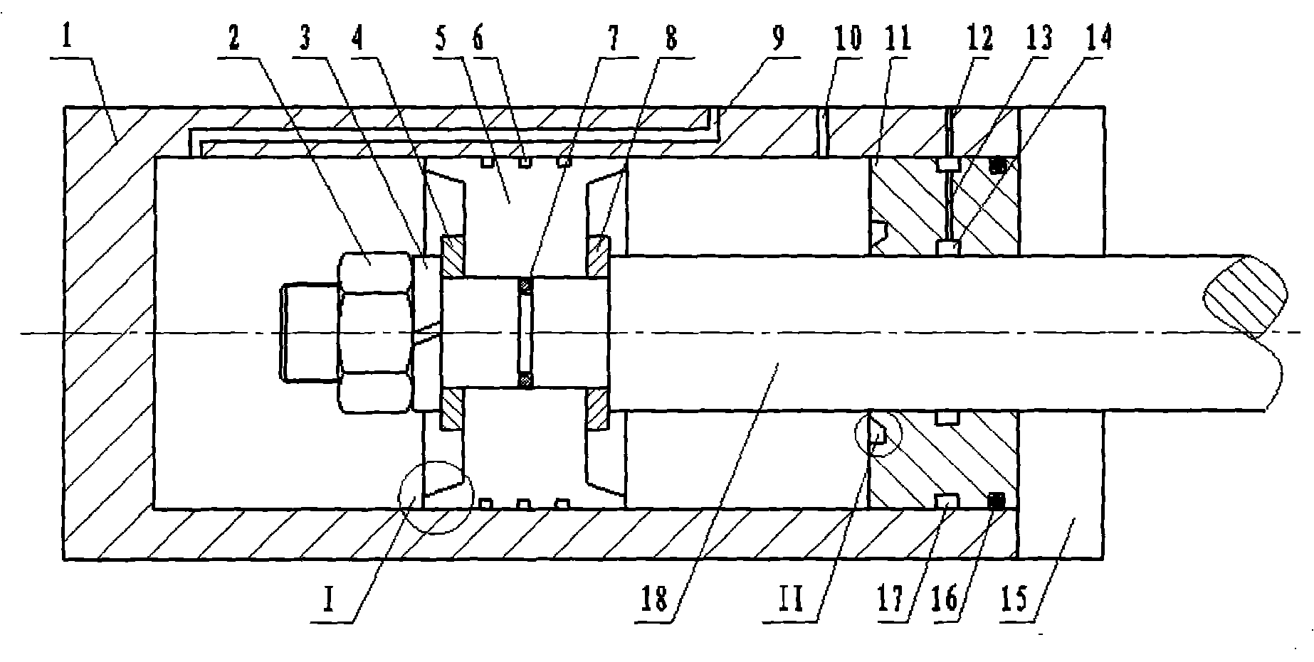
[0025] A deformed piston clearance sealed hydraulic cylinder, such as figure 1 As shown, the hydraulic cylinder includes a cylinder body 1, a piston 5, a piston rod 18, a guide sleeve 11 and an end cover 15. It is characterized in that 3 to 5 balance grooves 6 are evenly opened on the outer circle of the piston 5 symmetrically. The piston rod 18 of the piston 5 is provided with a first sealing groove 7 , and the end surfaces on both sides of the piston 5 are provided with annular bosses having the same outer diameter as the piston 5 .

[0026] The outer circle of the guide sleeve 11 is provided with a second sealing groove 16, and the inner circle and outer circle of the guide sleeve 11 are respectively provided with a first oil drain groove 14 and a second oil drain groove 17, and the first oil drain groove 14 passes through the second oil drain groove. The second oil drain passage 13 communicates with the second oil drain groove 17, the second oil drain groove 17 communicate...

Embodiment 2

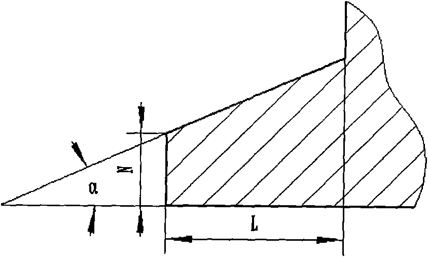
[0034] The utility model relates to a deformed piston gap sealing hydraulic cylinder. The shape of the ring boss is as figure 2 Shown, its section is a right-angled trapezoid, the included angle of the right-angled trapezoid is α=30~35°, the height of the right-angled trapezoid is L=8~12mm, and the length of the upper base of the right-angled trapezoid is N=1.2~1.5mm. The annular boss and the piston 5 are integral.

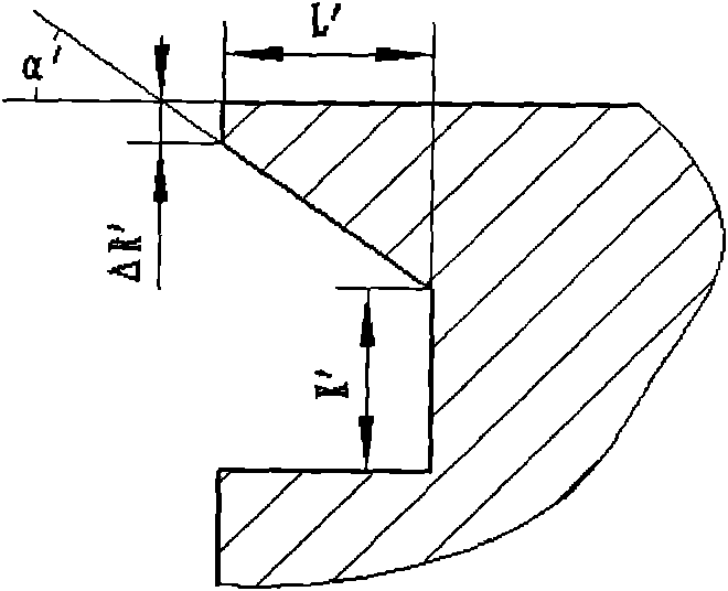
[0035] The annular groove on the inner end surface of the guide sleeve 11 is as image 3 As shown, the depth of the annular groove is L'=8~12mm, the bottom width of the annular groove is K'=8~10mm, the section of the annular groove is a right-angled trapezoid, and the included angle of the right-angled trapezoid is α'=30~35° ; The difference between the radius of the inner circle of the annular groove at the end surface and the radius of the inner circle of the guide sleeve 11 is ΔR'=1.3-1.5mm;

[0036] The groove width of the balance groove 6 on the piston 5 ...


PUM


Abstract

The invention particularly relates to a hydraulic cylinder with a clearance sealed type deformed piston, which adopts the following technical scheme that: an excircle of a piston [5] is uniformly and symmetrically provided with 3 to 5 balance slots [6]; a piston rod [18] of the piston [5] is provided with a first seal groove [7]; an annular boss of which the outer diameter is the same as that of the piston [5] is arranged on the end faces of two sides of the piston [5] respectively; an excircle of a guide sleeve [11] is provided with a second seal groove [16]; a first drain pan [14] and a second drain pan [17] are arranged on an inner circle and the excircle of the guide sleeve [11] respectively; the first drain pan [14] is communicated with the second drain pan [17] through a second oil drain channel [13]; the second drain pan [17] is communicated with a first oil drain channel [12] arranged on a cylinder body [1]; and an end face, close to the inner circle, of the inner side of the guide sleeve [11] is provided with am annular groove. The hydraulic cylinder has the characteristics of simple structure, convenient assembly and disassembly and maintenance, long service life, small friction, high frequency response, high reliability, external leakage prevention, and the like.

Description

technical field [0001] The invention belongs to the technical field of hydraulic cylinders. In particular, it relates to a deformed piston gap sealing hydraulic cylinder. Background technique [0002] Hydraulic cylinders, especially servo hydraulic cylinders, require low friction, no creep, high frequency response, long life, and high reliability to meet the static and dynamic performance requirements of hydraulic servo systems. Therefore, the sealing form and material selection between the piston and the cylinder, as well as the design of the guide sleeve and the selection of sealing materials are very important. [0003] At present, the more successful application is the rubber-plastic composite sealing ring composed of a square or rectangular cross-section non-metallic material ring and an O-shaped rubber ring. It has good wear resistance, oil resistance and heat resistance, and has a small friction coefficient. However, its assembly process is complicated, and a suppor...

Claims


Application Information

Patent Timeline
Patent Type & Authority Patents(China)
IPC IPC(8): F15B15/14
Inventor 湛从昌陈新元李成陈奎生蒋俊傅连东曾良才刘利明朱学彪付曙光
Owner WUHAN UNIV OF SCI & TECH
Why Eureka
Try Eureka