Thermal bridge dispersion type built-in thermal insulation concrete structure system

A technology of thermal insulation concrete and concrete structure, which is applied in the direction of thermal insulation, building components, building structure, etc. It can solve problems affecting the normal use and durability of buildings, the impact of indoor living environment, and mildew on the inner walls of houses, so as to ensure the internal Quality and appearance effect, reduce the influence of thermal bridge effect, good overall effect

Inactive Publication Date: 2011-12-14
河南省第一建设集团第七建筑工程有限公司 +2
View PDF0 Cites 0 Cited by
  • Summary
  • Abstract
  • Description
  • Claims
  • Application Information

AI Technical Summary

Problems solved by technology

The thermal bridge part not only has serious heat loss, but more importantly, water vapor will condense on its inner surface under certain conditions to form condensed water. If the condensed water stays for a long time and cannot be dissipated as soon as possible, the inner surface of the thermal bridge will absorb air. Dust and other substances in it, and the damp inner surface is very easy to breed mold and other microorganisms, resulting in mildew and hair growth on the inner wall of the house, which not only affects the normal use and durability of the building, but also has a direct impact on the indoor living environment. directly endanger people's physical and mental health

Method used


Image

  • Thermal bridge dispersion type built-in thermal insulation concrete structure system
  • Thermal bridge dispersion type built-in thermal insulation concrete structure system
  • Thermal bridge dispersion type built-in thermal insulation concrete structure system

Examples


Embodiment 1

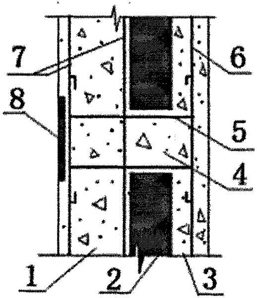
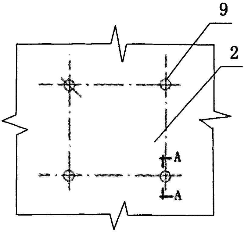
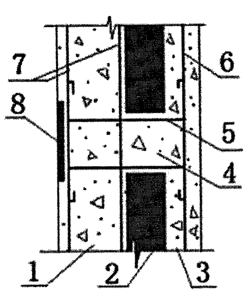
[0035] Embodiment 1 A thermal bridge dispersed built-in thermal insulation concrete structure system, see figure 1 , figure 2 , including load-bearing concrete structure layer 1, thermal insulation material layer (XPS insulation board) 2, concrete protection layer 3, concrete protection layer 3 (thickness 50mm) from inside to outside, its strength is not lower than C25, and the load-bearing concrete structure layer 1 It is connected with the concrete protective layer 3 through a certain number of tension bridges 4 that pass through the reserved holes 9 of the XPS insulation board 2 in a dispersed manner. 1500mm, the cross-section of the reserved hole 9 is circular (Φ80mm), the sum of the area of ​​the cross-section of all the reserved holes 9 accounts for 0.3-0.6% of the corresponding wall area, and the inner side of the load-bearing concrete layer 1 is set to block the reserved hole Inner insulation material layer (square XPS insulation board, side length 120mm, thickness 2...


PUM


Abstract

The invention relates to a thermal bridge dispersed built-in thermal insulation concrete structure system. It includes load-bearing concrete structure layer, thermal insulation material layer and concrete protection layer from the inside to the outside. There are reserved holes at regular intervals along the vertical and horizontal directions of the thermal insulation material layer. There are transverse steel bars, load-bearing concrete structure layer and concrete protection layer in the holes. The steel bars in it are connected to form a tension bridge with the poured concrete, and an inner insulation material layer slightly larger than the reserved hole is fixed on the inner side of the load-bearing concrete structure layer corresponding to the reserved hole. The invention can disperse the thermal bridge effect, balance the heat transfer of the building envelope, significantly reduce the thermal bridge effect, and have good thermal insulation performance; the built-in thermal insulation layer is safe to use and can last the same life as the structure, greatly exceeding the external thermal insulation system 25-year service life; it can eliminate hidden dangers such as easy cracks, hollowing, leakage, and shedding caused by the use of external wall paste and external insulation layers. It combines many advantages such as thermal insulation, earthquake resistance, environmental protection, short construction period, and low cost.

Description

technical field [0001] The invention relates to the field of engineering construction, in particular to a thermal bridge dispersed built-in thermal insulation concrete structure system. Background technique [0002] In the construction industry, the heat preservation technology and process of the building energy-saving and thermal insulation walls commonly used at present is that the formwork needs to be supported first, and the concrete wall is poured. After the concrete reaches a certain strength, the formwork is removed, and then the wall is made. Body insulation, usually using glue bonding method, paste the insulation board on the wall, or use steel wire or other materials to nail and hang the insulation board on the wall. After many complex processes, the exterior decoration is done. The construction process of this cast-in-place concrete and its wall insulation process is complicated, the speed is slow, and the wall is easy to crack and hollow. Poor thermal insulatio...

Claims


Application Information

Patent Timeline
Patent Type & Authority Patents(China)
IPC IPC(8): E04B1/76E04B1/80E04G21/02E04G21/12
Inventor 胡保刚陈震马发现鲁性旭高盼星郭建勇裴蕾职晓云
Owner 河南省第一建设集团第七建筑工程有限公司
Why Eureka
Try Eureka