Movable pin gear deceleration method and device

A technology of needle gear and live needle, which is applied in the direction of gear transmission, transmission, belt/chain/gear, etc.

Inactive Publication Date: 2010-07-28
陆文强
View PDF4 Cites 1 Cited by
  • Summary
  • Abstract
  • Description
  • Claims
  • Application Information

AI Technical Summary

Problems solved by technology

[0005] In order to solve the above-mentioned problems existing in existing measuring instruments, the present invention provides a method and device for reducing the speed of live needle gears

Method used


Image

  • Movable pin gear deceleration method and device
  • Movable pin gear deceleration method and device
  • Movable pin gear deceleration method and device

Examples


Embodiment Construction

[0025] The method and device for moving needle gear reduction of the present invention will be described in detail below in conjunction with the accompanying drawings, which are only illustrated as examples, and the scope of protection of the present invention should not be limited to the specific structure or specific number of components of the moving needle gear reduction device.

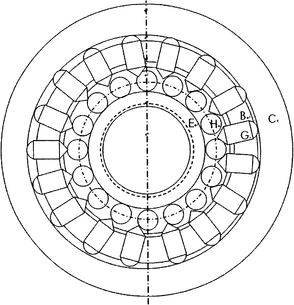
[0026] According to the first aspect of the present invention, there is provided a method for reducing the speed of the movable needle gear, which uses an eccentric wheel and a movable gear connected to the follower with the eccentric wheel, and utilizes n+1 movable needles in the movable needle fixed wheel The cooperation between the needle tooth cylinder and the n H needle tooth cylinders in the support frame of the deceleration pin gear E uses the extrusion of the eccentric wheel on the n+1 live needle tooth cylinders, so that the n+1 live needles are sequentially pressed against each other The...


PUM


Abstract

The invention provides a movable pin gear deceleration method and device. An eccentric wheel and a movable gear are used, wherein the movable gear and the eccentric wheel are connected to a follower; n+1 movable pin cylinders successively squeeze a pin gear cylinder contacting with the movable pin cylinders in order by the cooperation of n+1 movable pin cylinders in a movable pin fast pulley and n pin gear cylinders in the support frame of a deceleration pin gear as well as the extrusion to n+1 movable pin cylinders by the eccentric wheel; thus, the deceleration pin gear in the inner ring rotates in reverse direction or same direction to move the position of one cylinder period so as to finally obtain the result of changing the phenomenon that the peripheral eccentric wheel displaces for one cycle into the phenomenon that the inner deceleration pin gear parts displace for 1/n cycle in reverse direction or same direction.

Description

technical field [0001] The invention belongs to the field of variable speed of live needle gears, and in particular relates to a speed change method and device for extruding the radial movement of live needles by an eccentric wheel so that the live needles squeeze needle teeth, thereby realizing the deceleration of inner and outer circumferences by n times. Background technique [0002] It is currently known that the reduction transmission device in the traditional sense is mostly realized by the gear ratio of the driving and passive gears of the reduction gear. The axes of the driving and passive wheels of this kind of reduction gear are separated, and the occupied space and volume are relatively large, so it is not suitable to be realized in a small space. , and has the weakness of return stroke difference; the planetary gear deceleration load moment is too small. [0003] For example, Chinese patent application No. 200910104693 discloses a reduction transmission with few ...

Claims


Application Information

Patent Timeline
Patent Type & Authority Applications(China)
IPC IPC(8): F16H1/32
Inventor 陆文强谭成章
Owner 陆文强
Why Eureka
Try Eureka