Linear micro-motion mechanism

A technology of moving mechanism and driving mechanism, which is applied in the direction of mechanical equipment, transmission device, gear transmission device, etc.

Pending Publication Date: 2019-01-29
CHANGZHOU INST OF MECHATRONIC TECH
View PDF0 Cites 0 Cited by
  • Summary
  • Abstract
  • Description
  • Claims
  • Application Information

AI Technical Summary

Problems solved by technology

[0003] The technical problem to be solved by the present invention is to overcome the deficiencies of the prior art and provide a linear micro-motion mechanism to solve the problem of micro-movement of the actuator

Method used


Image

  • Linear micro-motion mechanism
  • Linear micro-motion mechanism
  • Linear micro-motion mechanism

Examples


Embodiment Construction

[0022] In order to make the content of the present invention more clearly understood, the present invention will be further described in detail below based on specific embodiments and in conjunction with the accompanying drawings.

[0023] Unless otherwise defined, the technical terms or scientific terms used herein shall have the usual meanings understood by those skilled in the art to which the present invention belongs. "First", "second" and similar words used in the patent specification and claims of the present invention do not indicate any order, quantity or importance, but are only used to distinguish different components. Likewise, words like "a" or "one" do not denote a limitation in quantity, but indicate that there is at least one.

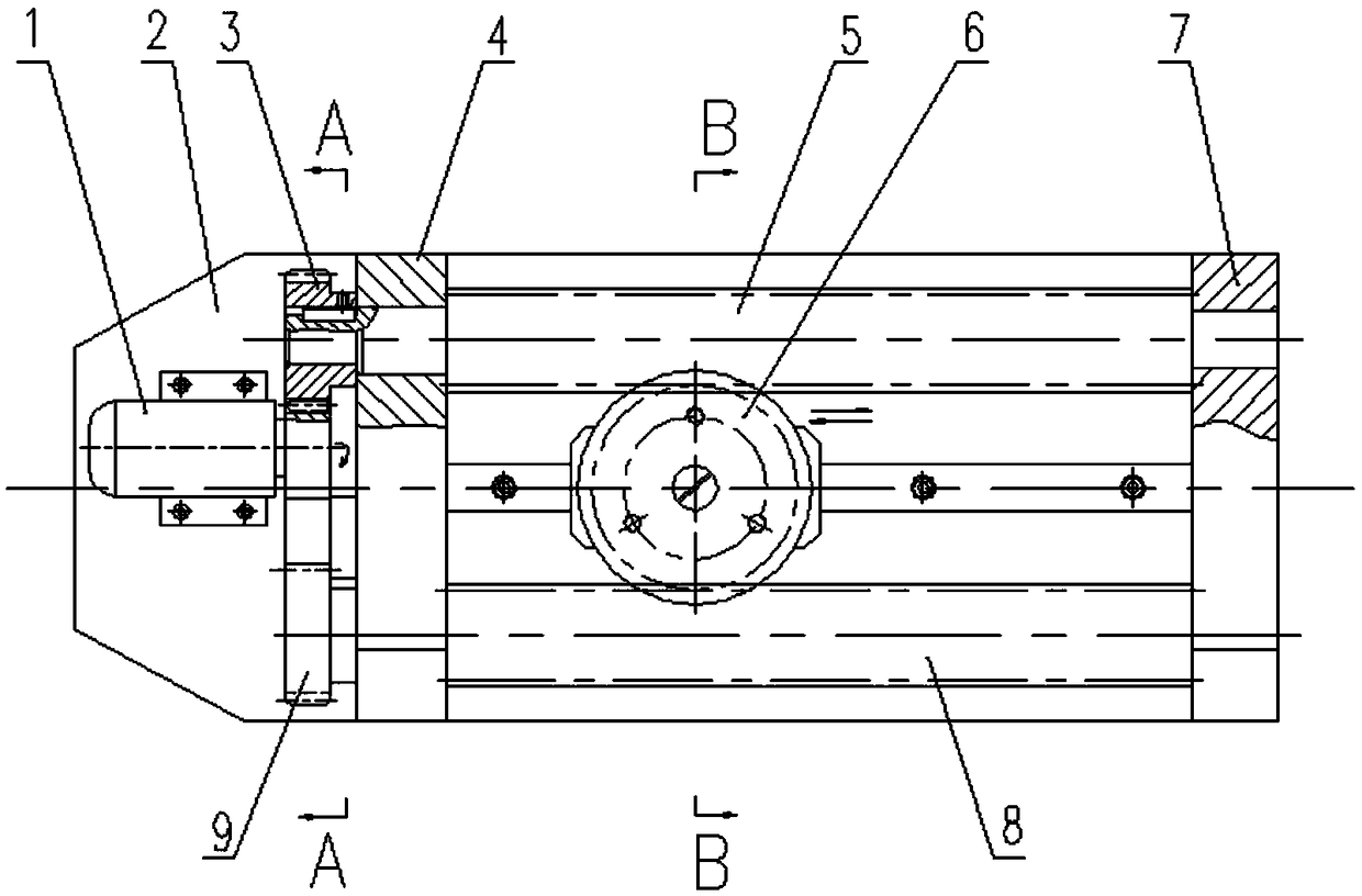
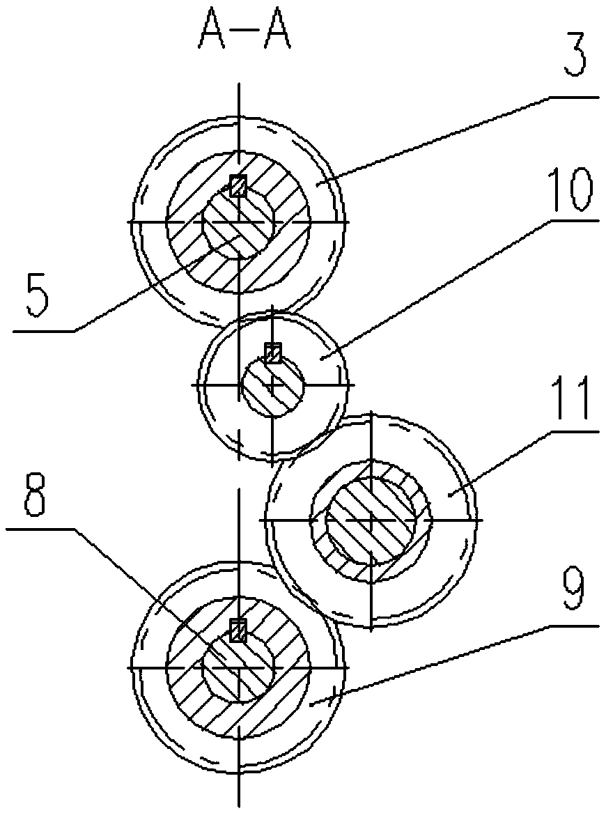
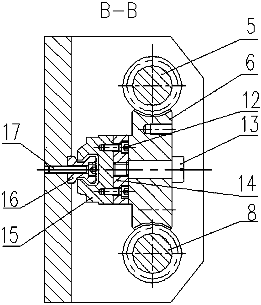
[0024] like Figure 1 to Figure 4 As shown, a linear micro-motion mechanism includes a frame seat, a driving mechanism, a worm gear and a guide rail.

[0025] The frame seat includes a base plate 2 , and a first support plate 4 and a ...


PUM


Abstract

The invention discloses a linear micro-motion mechanism. The linear micro-motion mechanism comprises a machine frame seat, a driving mechanism, a worm wheel and worm pair and a guide rail; the drivingmechanism is installed on the machine frame seat, and is used for driving a first worm and a second worm to rotate synchronously in opposite directions; the worm wheel and worm pair is composed of the first worm, the second worm and a worm wheel, and the first worm and the second worm are correspondingly arranged on the two sides of the worm wheel and are both meshed with the worm wheel; the wormwheel is rotationally installed on a middle piece through a rotating shaft, and the middle piece is assembled on the guide rail, and can slide along the guide rail; and the pitch difference delta between the axial pitch of the first worm and the axial pitch of the second worm is smaller than or equal to the meshing clearance alpha, and the first worm and the second worm enable the worm wheel to move along the guide rail through the pitch difference delta between the first worm and the second worm. According to the linear micro-motion mechanism, multiple stages of speed reducers are not needed, micro displacement of the worm wheel is achieved by utilizing the pitch difference of the worms, and an executing piece is installed on the worm wheel so that the requirement for micro displacementof the executing piece can be met.

Description

technical field [0001] The invention relates to a linear micro-motion mechanism. Background technique [0002] In some transmission structures that require linear micro-feeding, such as when the movement of the actuator needs to be less than 0.5mm per minute, a variable-speed motor is often used to cooperate with a multi-stage reducer, and then the micro-feeding is performed in the form of a screw nut. With such a structure, it often needs to be decelerated by more than two stages to meet the requirements. The mechanical transmission efficiency is low, the structure is large, and the cost is high, which is also not conducive to the miniaturization design of the mechanism. Using the screw nut structure, in addition to the use of a speed reducer, also requires a precise small pitch transmission between the screw rod and the nut, which brings inconvenience to processing and high processing costs. Contents of the invention [0003] The technical problem to be solved by the pr...

Claims


Application Information

Patent Timeline
Patent Type & Authority Applications(China)
IPC IPC(8): F16H1/22F16H1/24
CPCF16H1/225F16H1/24
Inventor 吴小邦靳敏马元
Owner CHANGZHOU INST OF MECHATRONIC TECH
Why Eureka
Try Eureka