Beam selection method

一种波束、选择装置的技术,应用在波束选择领域,能够解决下降链路性能、有误差等问题

Inactive Publication Date: 2010-08-18
SONY CORP
View PDF6 Cites 16 Cited by
  • Summary
  • Abstract
  • Description
  • Claims
  • Application Information

AI Technical Summary

Problems solved by technology

[0008] A disadvantage of prior art beamforming methods using the identity matrix approach is that for antenna arrangements with a small number of antennas (e.g. less than 8), there are rows and columns of the identity matrix when some antenna elements do not work as expected some orthogonal problems of
[0012] Second, there is sometimes an error when the wrong coarse beam is chosen in the early steps when the best optimal thin beam lies between two coarse beams
This eventually leads to non-optimal beamlet selection in subsequent steps and degraded link performance

Method used


Image

  • Beam selection method
  • Beam selection method
  • Beam selection method

Examples


Embodiment Construction

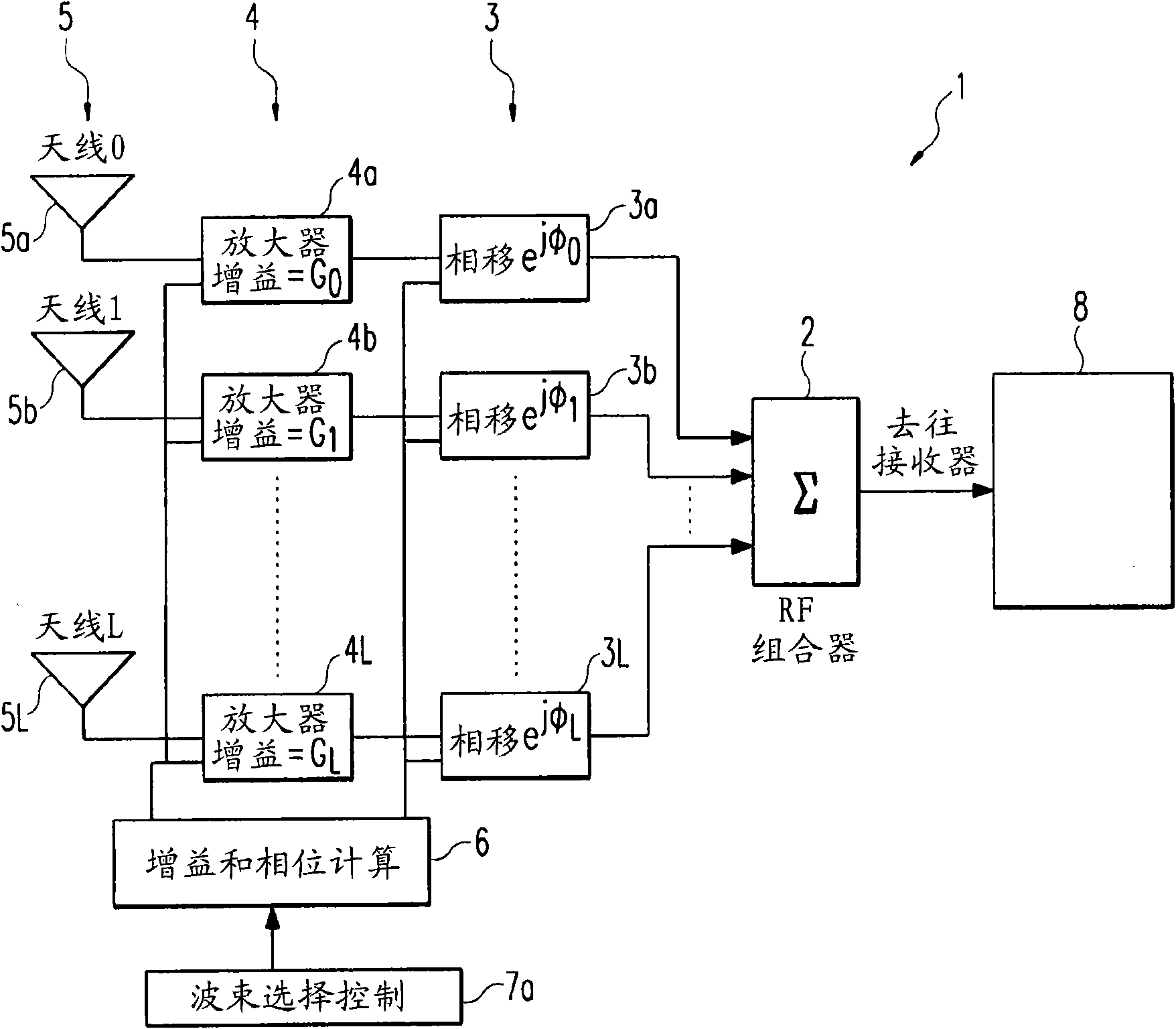
[0043] The invention relates to a beam selection method for a transmitter / receiver pair of a communication system using antenna beams.

[0044] In particular, specific criteria are used to support the selection process. For example, certain measurements are made at the receiver on the estimated channel delay profile for each different antenna combination or also called antenna beam arrangement. A combination is defined by a specific directional transmitter beam and / or a specific directional receiver beam establishing a link or at least allowing measuring the presence of the respective beam.

[0045] The delay spread shown by the channel delay profile is a type of distortion caused when the same signal arrives at its destination at different times. Signals usually pass through multiple paths and arrive at different angles of arrival. in usually line of sight The time difference between the instant of arrival of the first multipath component of a component and the instant ...


PUM


Abstract

The present invention relates to a method which analysis the characteristics of the received signal and selects the best beam arrangement for a transmitter / receiver pair for a given situation in a communication system. In particular, the channel delay profile provides characteristics which help to determine and evaluate the quality of a signal link. The result of this evaluation is used for selecting the best beam arrangement.

Description

technical field [0001] Many communication systems use antenna beaming (or adaptive beamforming) for radio communication systems to increase the signal-to-noise ratio (SNR). Alternatively, if interference is present, antenna beams are typically used to increase the signal-to-interference-plus-noise ratio (SINR) by increasing the power of the desired signal and / or reducing the power of the undesired interference. [0002] However, the challenge is how to analyze, determine and / or select the best beam combination for a given transmitter / receiver pair. [0003] First, there may be multiple antenna beam combinations that need to be tested. If it is assumed that the beamsets at the transmitter and receiver have Q possible beams each producing Q different radiation patterns, the total number of possibilities for a transmitter / receiver pair is Q 2 . This means that even for small antenna arrays with a limited number of possible radiation patterns, the total number of possible combi...

Claims


Application Information

Patent Timeline
Patent Type & Authority Applications(China)
IPC IPC(8): H04W16/28H04W24/00
CPCH04B7/0695H04B7/088
Inventor R·斯特林-加拉赫J·诺古伊拉-宁
Owner SONY CORP
Why Eureka
Try Eureka