Supercharge Your Innovation With Domain-Expert AI Agents!

Resource allocation method in communication system, resource allocation system, and base station used for the same

A resource allocation and communication system technology, applied in the field of resource allocation, resource allocation systems and base stations used in communication systems, can solve the problems of inability to increase the number of associated terminals, large amount of signaling information, and limited number of terminals, etc.

Inactive Publication Date: 2010-09-22
NEC CORP
View PDF3 Cites 1 Cited by
  • Summary
  • Abstract
  • Description
  • Claims
  • Application Information

AI Technical Summary

Problems solved by technology

[0004] Dynamic scheduling enables resource allocation according to channel quality, and thus high throughput can be expected; however, due to the large amount of signaling information, the number of terminals transmitting simultaneously within 1 TTI is limited
Therefore, in the case of regularly generating traffic, when the size of one packet is small and traffic such as VoIP (Voice over IP) traffic is generated at regular intervals, there is a problem that since the number of terminals simultaneously transmitting is limited, Therefore despite having a sufficient number of allocatable RBs, the number of associated terminals (users) cannot be increased

Method used


Image

  • Resource allocation method in communication system, resource allocation system, and base station used for the same
  • Resource allocation method in communication system, resource allocation system, and base station used for the same
  • Resource allocation method in communication system, resource allocation system, and base station used for the same

Examples


no. 1 example

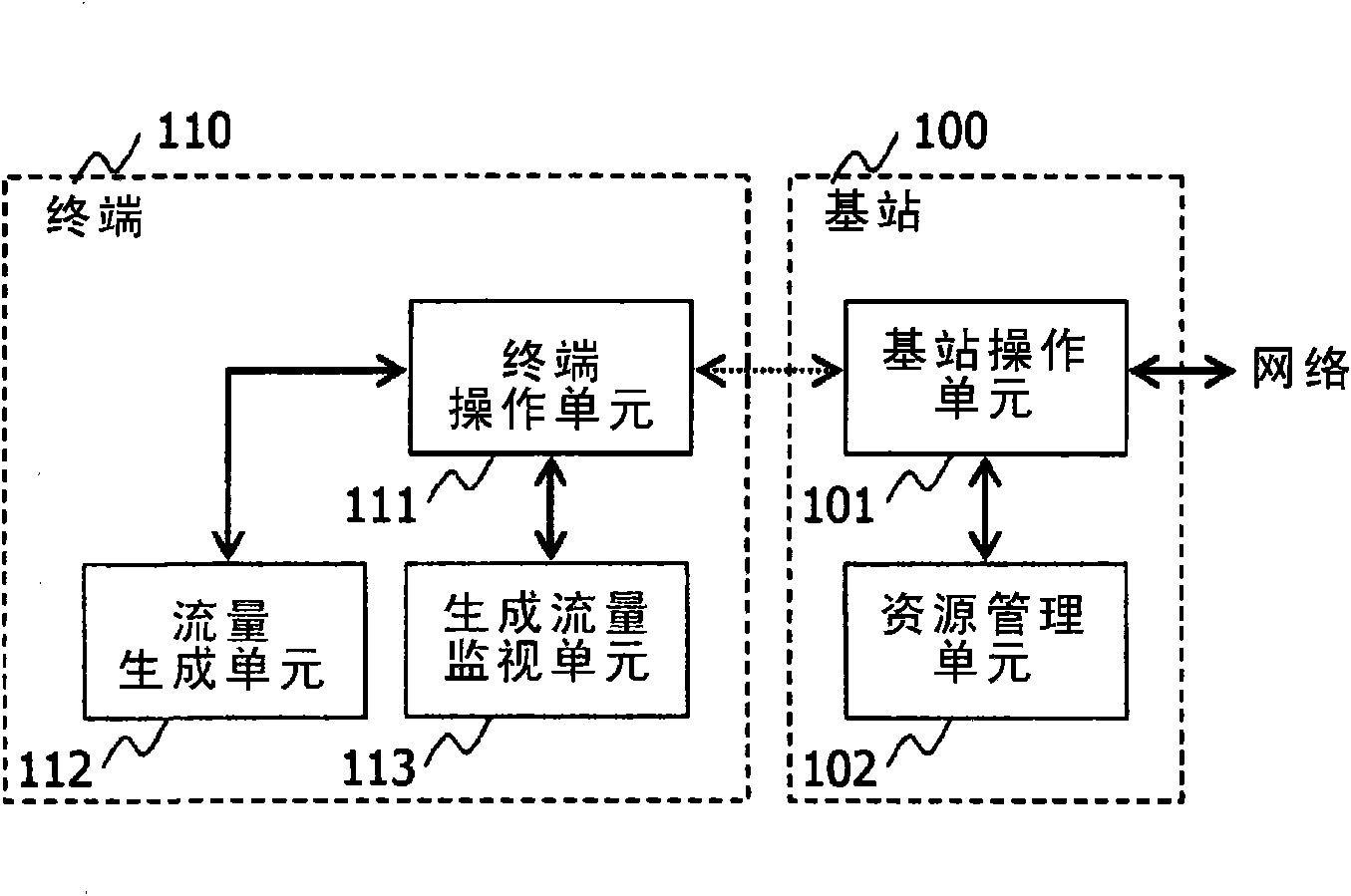
[0085] figure 1 is a diagram showing one example of the basic configuration of a communication system to which the present invention is applied. In this embodiment, the communication system is described by taking the uplink of LTE as an example. refer to figure 1 , the communication system includes a base station 100 and a terminal 110 . The base station 100 is connected to the terminal 110 through a radio channel. Base station 100 is connected to a network not shown. Also, although not shown, the base station 100 can be connected to a plurality of terminals. Additionally, there may be multiple base stations.

[0086] refer to figure 1 , the base station 100 includes a base station operating unit 101 and a resource management unit 102 . The terminal 110 includes a terminal operation unit 111 , a traffic generation unit 112 and a generated traffic monitoring unit 113 . The base station operating unit 101 has functions similar to those of a base station generally used...

no. 2 example

[0126] A second embodiment of the present invention is described below. Figure 9 is a diagram showing one example of the basic configuration of the communication system according to this embodiment, and is related to figure 1 Elements that are equivalent to those in are denoted by the same reference numerals. Will Figure 9 configuration with figure 1 In comparison, the difference is that the traffic generating unit 112 in the terminal 110 is removed, and the traffic generating device 120 is added to the outside of the terminal 110 instead.

[0127] The traffic generating device 120 has the figure 1 The function of the traffic generation unit 112 is similar to the function. In addition, the terminal 110 and the traffic generating device 120 are connected by a radio link. For example, in the case where the traffic generating device 120 is a personal computer, the terminal 110 is a wireless modem, the two are connected by a radio link such as Bluetooth (registered trade...

no. 3 example

[0130] A third embodiment of the present invention is described below. Figure 10 is a diagram showing one example of the basic configuration of the communication system according to this embodiment, and is related to figure 1 Elements that are equivalent to those in are denoted by the same reference numerals. Will Figure 10 configuration with figure 1 In comparison, the difference is that the generation traffic monitoring unit 113 is removed, and the transmission traffic monitoring unit 114 is added to the terminal 110 instead.

[0131] The transmission traffic monitoring unit 114 has a function of monitoring the transmission state of the traffic and reporting the monitoring result to the base station 100 . In addition, the resource management unit 102 has a resource usage status that monitors a reception status from traffic in addition to the function in the first embodiment.

[0132] Next, operations according to this embodiment are described with reference to the dr...


PUM


Abstract

It is possible to provide a resource allocation method in a communication system which can effectively suppress a transmission delay. Provided is a resource allocation system in a communication system which includes a terminal (110) and a base station (100), wherein data is regularly generated at the terminal, the base station allocates a resource to the terminal, and the terminal transmits data by using the resource. The terminal (110) has a generated traffic monitoring unit (113) which monitors the data. When a predetermined change is generated in the data, the monitoring unit (113) reports it to the base station. The base station (100) has a resource management unit (102) which decides a resource allocation according to the report from the terminal.

Description

technical field [0001] The present invention relates to a resource allocation method in a communication system, a resource allocation system and a base station used in the resource allocation system, and more particularly relates to a resource allocation technology in a communication system that regularly generates traffic. Background technique [0002] In the uplink of LTE (Long Term Evolution), which 3GPP (Third Generation Partnership Project) advocates its standardization, both so-called dynamic scheduling and persistent (persistent) scheduling are under consideration as scheduling schemes (see Non-Patent Literature 1). [0003] The former dynamic scheduling is scheduling that allocates resources to communication terminals (hereinafter simply referred to as terminals) for 1 TTI (Transmission Time Interval). The resource indicates RB (Resource Block) and MCS (Modulation Coding Scheme). An RB is the smallest unit of frequency resources that can be allocated to one TTI. I...

Claims


Application Information

Patent Timeline
Patent Type & Authority Applications(China)
IPC IPC(8): H04W24/00H04W72/04H04W72/12
CPCH04W72/0413H04W24/00H04W72/04H04W88/08H04W72/21
Inventor 信清贵宏李琎硕
Owner NEC CORP
Features
  • R&D
  • Intellectual Property
  • Life Sciences
  • Materials
  • Tech Scout
  • Unparalleled Data Quality
  • Higher Quality Content
  • 60% Fewer Hallucinations
Learn More