
Cotton collecting device of roving machine

A roving frame and cotton collecting technology, which is applied in the direction of textiles and papermaking, can solve the problem that waste flowers cannot be scraped off, and achieve the effect of preventing sagging and good cotton collecting effect

Active Publication Date: 2011-12-28
CMT HICORP MACHINERY QINGDAO
View PDF0 Cites 0 Cited by
  • Summary
  • Abstract
  • Description
  • Claims
  • Application Information

AI Technical Summary

Problems solved by technology

[0003] The task of the present invention is to solve the technical problem that the above-mentioned waste flowers attached to the upper part of the inner tank wall of the roving frame cannot be scraped in the prior art roving frame cotton collecting device, and to provide a roving frame cotton collecting device

Method used


Image

  • Cotton collecting device of roving machine
  • Cotton collecting device of roving machine
  • Cotton collecting device of roving machine

Examples


Embodiment Construction

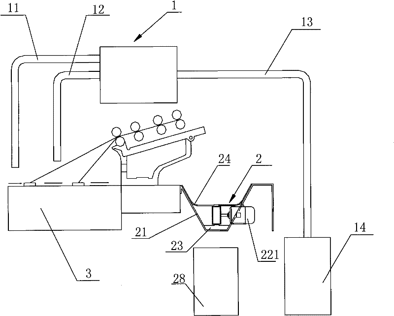
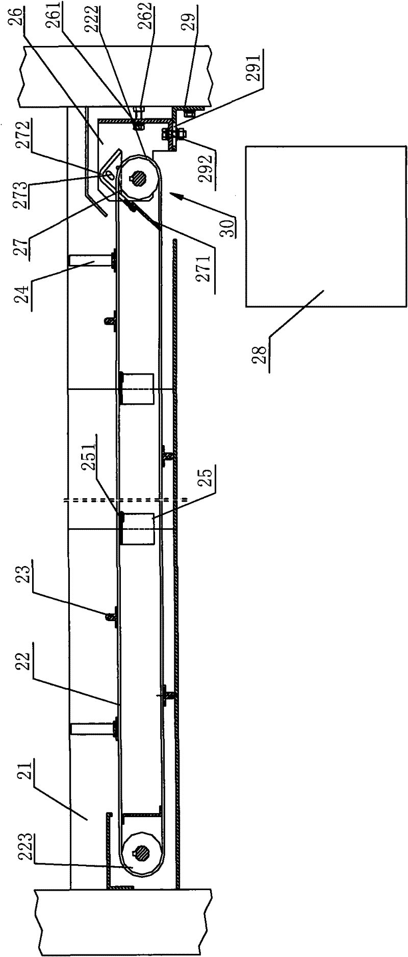
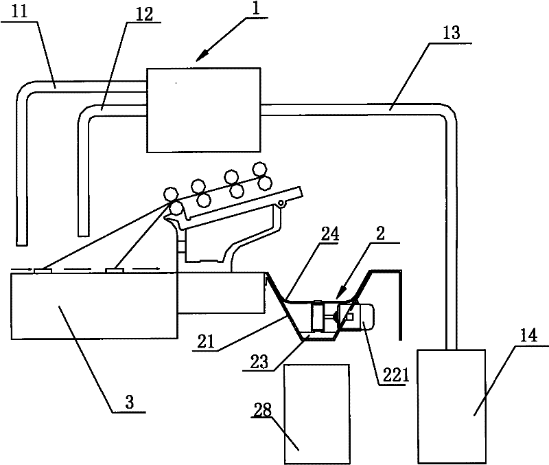
[0022] combine figure 1 and figure 2 , a roving frame cotton collection device, comprising a blowing and suction cleaner 1 located above a roving frame body 3 and a cotton collector 2 located at the rear side of the roving frame body 3 . Above-mentioned blowing and sucking cleaner 1 is provided with blowing pipe 11, suction pipe 12, dust discharge pipe 13 and suction fan 14, and the nozzle of blowing pipe 11 and suction pipe 12 is towards roving machine body 3, and dust discharge pipe 13 is connected with suction blower. Fan 14 is connected. The waste flowers on the roving frame body 3 are blown up by the blowing pipe 11 of the above-mentioned blowing cleaner, and part of the blown waste flowers are inhaled through the suction pipe 12 of the blowing cleaner, and then passed through the dust discharge pipe. 13 is discharged under the effect of suction fan 14. The cotton collector 2 is used to collect a part of the waste flowers that are blown up and transferred to the rear ...


PUM


Abstract

The invention discloses a cotton collecting device of a roving machine, comprising a blowing and suction cleaner and a cotton collector, wherein the blowing and suction cleaner is positioned above a machine body; the cotton collector is positioned at the rear side of the machine body; the blowing and suction cleaner is provided with an air blowing pipe, an air suction pipe and a dust discharging pipe, wherein pipe orifices of the air blowing pipe and the air suction pipe face toward the machine body of the roving machine; the cotton collector is provided with a cotton collecting groove which is opened upwards and a rotary type annular belt which stretches along the length direction of the cotton collecting groove; and the body of the rotary type annular belt is provided with a clean scraping plate which is appropriate to the bottom inside the cotton collecting groove. The cotton collecting device is characterized in that the body of the rotary type annular belt is also provided with flexible elastic scraping strips which can scrape cotton wastes attached to the inner walls of both sides of the cotton collecting groove; the belt body carrying with the flexible elastic scraping strips can repeatedly continuously scrape from one end of the cotton collecting groove to the other end of the cotton collecting groove simultaneously along the inner walls of both sides of the cotton collecting groove in the rotary process of the rotary type annular belt, and the cotton wastes attached to the inner walls of both sides of the cotton collecting groove are scraped to drop into the bottom inside the cotton collecting groove. The invention is convenient for the synchronous scrape of the clean scraping plate and beneficial to keeping better cotton collecting effect.

Description

technical field [0001] The invention relates to a roving frame in a textile machine, in particular to a cotton (dust) collecting device used in the roving frame. Background technique [0002] The cotton collecting device used in the roving frame in the prior art is also called a dust collecting device, which includes a suction cleaner located above the roving frame body and a cotton collector located at the rear side of the frame. The blowing and suction cleaner is provided with a blowing pipe, a suction pipe and a dust discharge pipe. The nozzles of the blowing pipe and the suction pipe face the roving frame body, and the dust discharge pipe can be connected with the suction fan. The cotton collector is provided with a cotton collecting trough with an opening facing upwards, a rotary endless belt extending along the length of the cotton collecting trough, and a cotton collecting box located below one end of the cotton collecting trough. The hard block-shaped cleaning scrap...

Claims


Application Information

Patent Timeline
Patent Type & Authority Patents(China)
IPC IPC(8): D01H11/00
Inventor 王成吉李建霞崔桂华王森栋任义利
Owner CMT HICORP MACHINERY QINGDAO
Learn More