Lateral punching device

A lateral punching and cutting knife technology is applied in the field of punching devices for laterally punching and cutting products to be cut to achieve the effects of reducing production costs and improving production efficiency

Active Publication Date: 2010-12-15
NINGBO XINTAI MACHINERY
View PDF6 Cites 6 Cited by
  • Summary
  • Abstract
  • Description
  • Claims
  • Application Information

AI Technical Summary

Problems solved by technology

As for the above-mentioned bright strips, since they need to play a decorative role, the requirements for the surface of the product are very high, and the surface of the product cannot be damaged during the punching process, so this device is not suitable for punching products that have high requirements for the surface.

Method used


Image

  • Lateral punching device
  • Lateral punching device
  • Lateral punching device

Examples


Embodiment Construction

[0026] The present invention will be further described in detail below in conjunction with the accompanying drawings and embodiments.

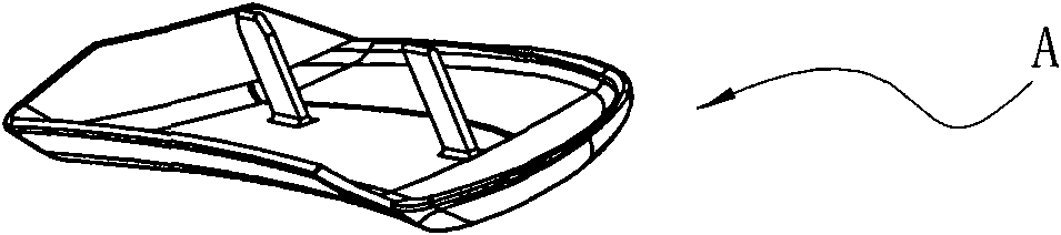
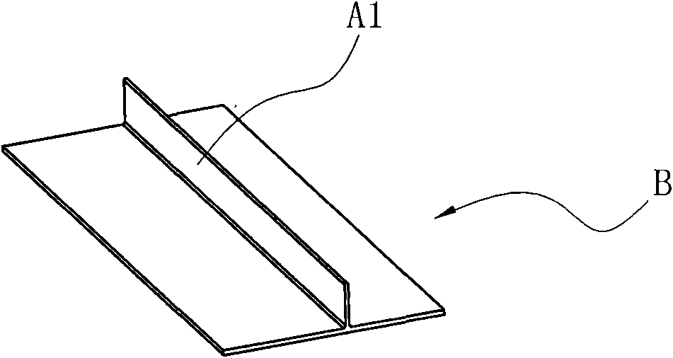
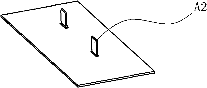
[0027] like Figure 1 to Figure 3 as shown, figure 1 It is a triangular bright strip A for auto parts. The lower surface of the extruded semi-finished product B has ribs A1 and forms a T-shaped structure as a whole. Now it is necessary to punch off part of the ribs to form two separate sheet-shaped chucks. A2. In order to achieve the above requirements, a lateral punching device is now used, such as Figure 4 As shown, the device includes an upper template 1, a lower template 2, and a guide post 3 arranged between the upper template 1 and the lower template 2, wherein the upper template 1 can move downward through the guide post 3, and an inclined frame is installed on the upper template. The wedge 4 and the binder plate 5 are fixed with a guide rail 6 on the lower formwork 2, and a slide block 7 is installed on the guide rail 6. The slide ...


PUM


Abstract

The invention relates to a lateral punching device comprising an upper template, a lower template, a placing table and a cutter, wherein the placing table is used for placing a to-be-cut product with a fillet; an inclined wedge block and a pressure plate corresponding to the placing table are installed on the upper template; a slide block driven by the inclined wedge block and a first spring for resetting the slide block are arranged on the lower template; and the cutter is installed on the slide block. The lateral punching device is characterized in that the placing table comprises a first placing table and a second placing table which are oppositely distributed, a gap in which the fillet is inserted is formed between the first placing table and the second placing table, the cutter is positioned under the first placing table at one side of the fillet, and a stop block corresponding to the fillet and deviating from the cutter is installed on the second placing table positioned at the other side of the fillet. Because the lateral punching device is not provided with a die, the to-be-cut product is pressed by the pressure plate, and the punching force is blocked by the stop block, wastes are scraped finally, therefore, the lateral punching device can keep the appearance surface of the to-be-cut product better so that products which can not be punched by the common punching device originally can smoothly realize lateral punching, and the lateral punching device can improve the production efficiency and reduces the making cost.

Description

technical field [0001] The invention relates to a punching device, in particular to a punching device for laterally punching a product to be cut. Background technique [0002] There are various decorative strips on the car, such as triangular bright strips, such as figure 1 As shown, when the bright strip is produced, it is first extruded from aluminum material into a semi-finished product B with a T-shaped cross section, as shown in figure 2 As shown, the semi-finished product B is placed on a special milling machine, and the rib A1 is milled to form the following image 3 Sheet body chuck A2 shown. In the above processing process, although the desired product can be obtained in the end, due to the milling of the product on a special milling machine, the milling time is long, the production efficiency is low, and the investment of the special milling machine and the special milling fixture is too large, which eventually leads to product manufacturing. High cost defects....

Claims


Application Information

Patent Timeline
Patent Type & Authority Applications(China)
IPC IPC(8): B21D28/02B21D28/04
Inventor 何刚亚黄红星成维发
Owner NINGBO XINTAI MACHINERY
Why Eureka
Try Eureka