Ram bending deformation two-way compensating device

A two-way compensation, flexural deformation technology, used in other manufacturing equipment/tools, large fixed members, metal processing machinery parts, etc., can solve the problem of ram axial deformation and other problems, and achieve the effect of small rated pressure

Inactive Publication Date: 2010-12-15
通用技术齐齐哈尔二机床有限责任公司
View PDF4 Cites 18 Cited by
  • Summary
  • Abstract
  • Description
  • Claims
  • Application Information

AI Technical Summary

Problems solved by technology

[0004] In order to overcome the deficiencies of the existing tie rod compensation device that the ram is deformed axially due to the eccentricity of the tie rod, the present invention provides a two-way compensatio...

Method used


Image

  • Ram bending deformation two-way compensating device
  • Ram bending deformation two-way compensating device
  • Ram bending deformation two-way compensating device

Examples


Embodiment Construction

[0010] The present invention will be further described below in conjunction with accompanying drawing:

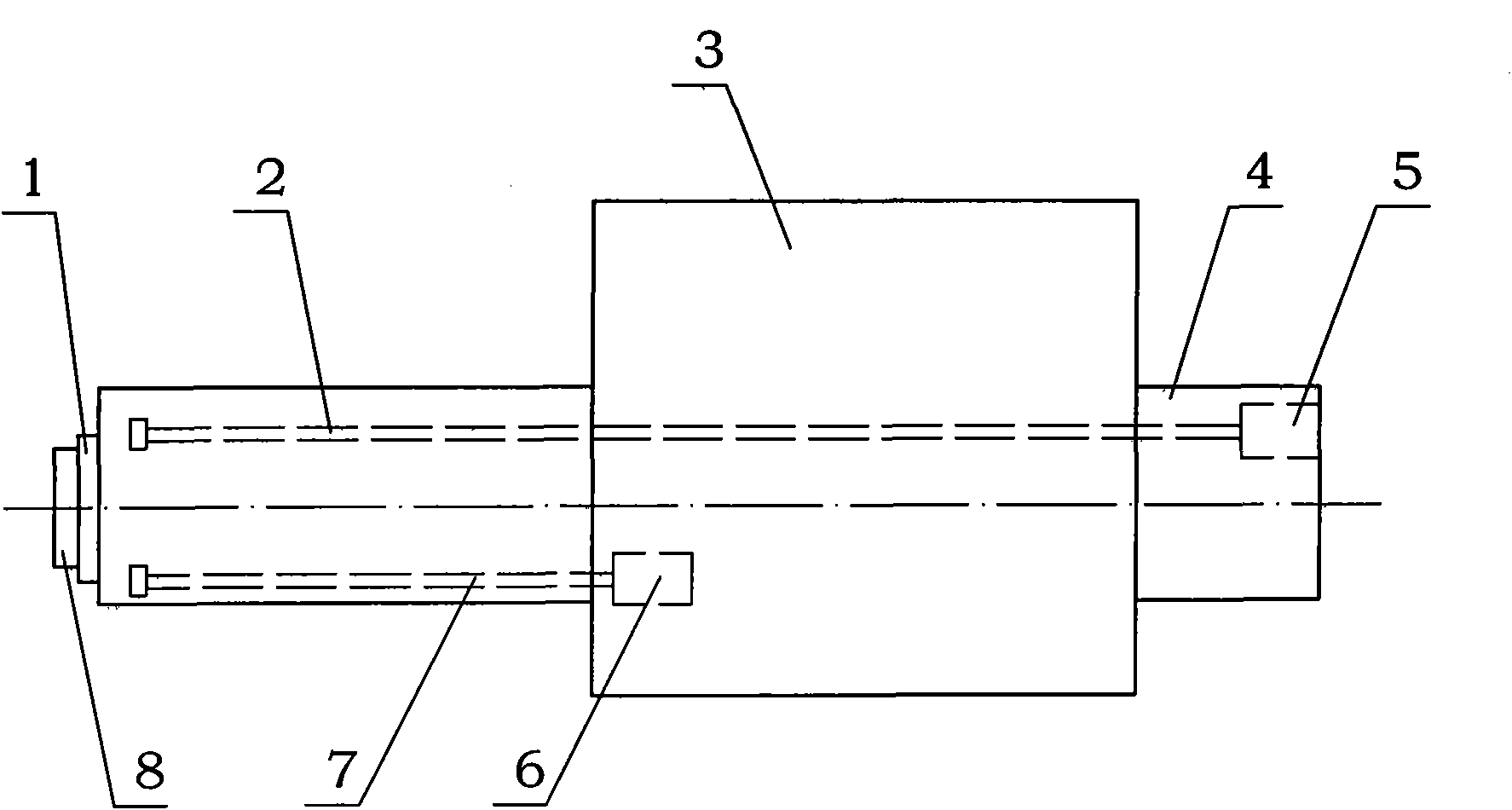
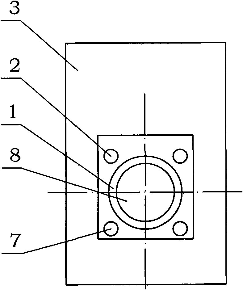
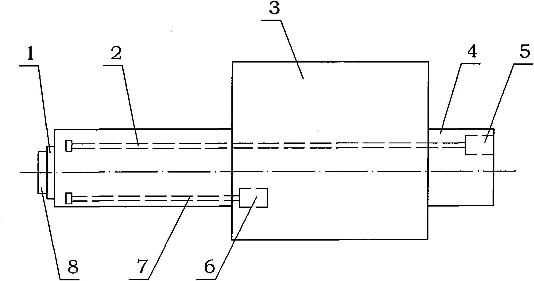
[0011] Depend on figure 1 combine figure 2 As shown, a two-way compensation device for deflection and deformation of a ram includes two pull rods 2 and a tension cylinder 5 connected thereto, a spindle box 3, and a ram 4. The two pull rods 2 are left and right symmetrical along the center line of the milling shaft 1, and the tension cylinder 5 Simultaneously control two pull rods 2. There are two pressure rods 7 and a thrust cylinder 6 connected with the pressure rods 7 at the lower part of the ram 4. The thrust cylinder 6 controls two pressure rods 7 at the same time. The horizontal plane where the center line of the milling shaft 1 is located is symmetrical up and down, and the two pressure rods 7 are left and right symmetrical along the center line of the milling shaft 1, that is, the plane formed by the two pull rods 2 and the plane formed by the two pressure rods 7 r...


PUM


Abstract

The invention relates to a ram bending deformation two-way compensating device, mainly solving the problem that the traditional draw bar compensating device causes the axial deformation of a ram because draw bars are eccentric. The invention is characterized in that the lower part of the ram (4) is provided with two compression bars (7) and a push action cylinder (6) connected with the compression bars (7); the compression bars (7) and the draw bars (2) are symmetrical up and down along the centre line of a milling spindle (1); the two compression bars (7) are symmetrical left and right along the centre line of the milling spindle (1); and the push action cylinder (6) is arranged in a main spindle box (3). The two-way compensating device does not generate the additional axial deformation while compensating the bending deformation of the ram. Compared with the traditional pure draw bar compensating method, the pressure required to be provided for the cylinder is small under the condition of compensating the same deflection, and therefore, the required rated pressure of the cylinder is smaller.

Description

Technical field: [0001] The invention belongs to the technical field of mechanical manufacturing, and in particular relates to a bidirectional compensating device for deflection and deformation of a ram of a floor milling and boring machine. Background technique: [0002] The most important structural feature of the floor milling and boring machine is the use of cantilevered ram working parts. The ram is in an overhang state when it is working, and the greater the working stroke, the greater the maximum overhang. Due to the weight factor of the ram itself and its main shaft and other accessories, the ram will inevitably produce deflection deformation during the extension process, thereby causing a certain deflection deformation at the working end of the main shaft, and this deflection deformation will cause the main shaft to rotate when it is working These errors are sufficient to affect the geometric shape accuracy and surface quality of the machined workpiece. Therefore,...

Claims


Application Information

Patent Timeline
IPC IPC(8): B23Q23/00B23Q1/01B23P23/02
Inventor 曲波吴凤和王跃宏
Owner 通用技术齐齐哈尔二机床有限责任公司
Why Eureka
Try Eureka