Peeler with self-adjusting rollers

A technology of power rollers and idler rollers, which is applied in the field of roller-type shrimp peeling machinery, and can solve problems such as loosening of fasteners

Active Publication Date: 2011-02-02
LAITRAM LLC
View PDF7 Cites 27 Cited by
  • Summary
  • Abstract
  • Description
  • Claims
  • Application Information

AI Technical Summary

Problems solved by technology

These manual readjustments need to be done fairly frequently and fasteners

Method used


Image

  • Peeler with self-adjusting rollers
  • Peeler with self-adjusting rollers
  • Peeler with self-adjusting rollers

Examples


Embodiment Construction

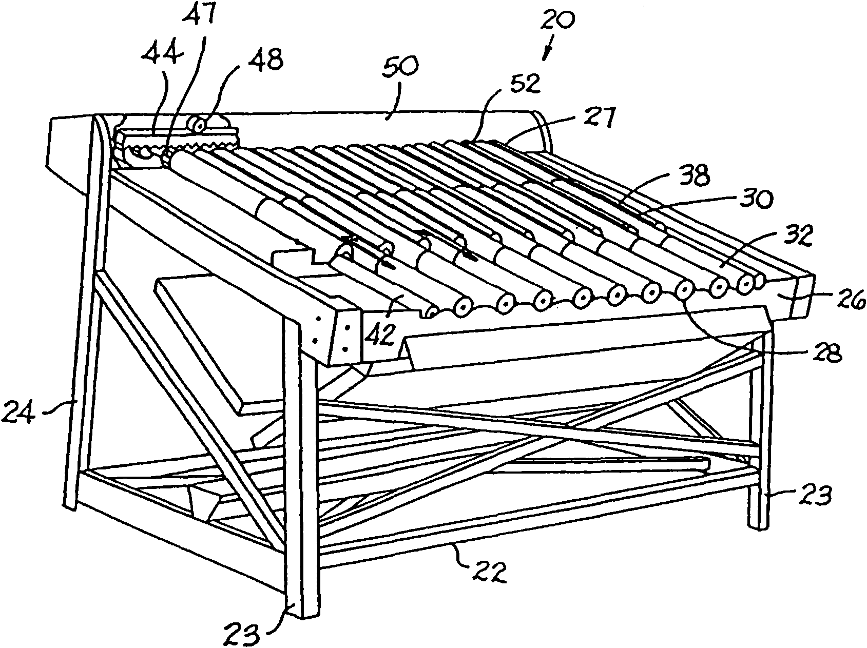
[0014] An illustrative example of a dehulling device having features of the invention is found in figure 1 shown in . A shelling apparatus 20 typically used to shell shrimp comprises a frame 22 comprising front and rear legs 23, 24 forming a frame structure with various cross braces and support elements. Platform 26 supports shelling rollers that slope downward from a first product inlet end 27 to a second product outlet end 28 (to simplify the drawing, the fingers normally used to push the shrimp into the shelling position are not shown) . figure 1 The rollers shown include two types of driven rollers: a groove forming roller 30 and a power roller 32 . In the upper shelling section of the shelling device, a plurality of side-by-side shelling grooves are formed by powered rollers 32 flanking two groove-forming rollers 30 . All of these rollers forming each upper groove are directly powered by the dehuller drive system. Each of these rollers is made of a tube (usually steel...


PUM


Abstract

Peeling apparatus and a method for biasing lower idle rollers of a roller-type peeling machine against power rollers to maintain the rollers in contact as the rollers wear. The apparatus includes biasing means, such as a cylinder applying upward pressure against the upper ends of the lower rollers to keep the rollers in constant contact.

Description

technical field [0001] The present invention relates to shelling apparatus, and more particularly to a roller shelling machine with a self-adjusting lower roll. Background technique [0002] The Shrimp Peeler was originally introduced due to the high labor cost of manually peeling small shrimps, and now the Shrimp Peeler has been widely used in the shrimp processing industry. In particular, roller shellers dominate the bulk shelling industry. US Patent No. 2,778,055 of January 22, 1957 and US Patent No. 2,537,355 of January 9, 1951 to Fernand S., James M. and Emile M. Lapeyre describe the basic structure and operation of the roller shrimp sheller principle. [0003] US patent US 2,778,055 shows a dehulling machine with a rigid frame supporting dehulling elements. The beam divides the dehuller into two dehulling sections. The upper shelling section extends from the rear wall to the beam; the lower shelling section extends from the beam to the lower front end of the shelle...

Claims


Application Information

Patent Timeline
IPC IPC(8): A22C29/02
CPCA22C29/026
Inventor 小J·温伯利
Owner LAITRAM LLC
Why Eureka
Try Eureka