Double-permanent magnet outer-rotor permanent magnet biased radial magnetic bearing

A technology of permanent magnetic bias and double permanent magnets, which is applied in the direction of bearings, shafts and bearings, shafts, etc., can solve the problems of magnetic interference of other components, increase the volume of the device, and complicate compensation methods, so as to reduce the residual magnetic moment and overcome the problems Sophisticated, easy to install and reliable results

Inactive Publication Date: 2011-03-30
BEIHANG UNIV
View PDF6 Cites 20 Cited by
  • Summary
  • Abstract
  • Description
  • Claims
  • Application Information

AI Technical Summary

Benefits of technology

This new technology uses two different ways for creating a strong magnesis system inside a flying wheel's structure called the external magneive rings (EMS). These EMR systems are designed differently from previous designs where they were used only on one side or another instead of being symmetrically located around their center point. By doing this, there can be fewer components needed compared to traditional methods like cushion mountings or rubber seals. Additionally, these techniques help reduce any remaining unbalanced force caused by gravity when turning at high speeds. Overall, this innovative technical solution improves efficiency and reliability during flight operations while also addressing issues such as increased size due to added materials required.

Problems solved by technology

Technological Problem: Current technical problem addressed in this patents relates to improving the reliability and efficiency (M/H) of magnelectrostatic thrust or electricity controlled flying wheel systems while reducing their overall weight without compromising their function capabilities. Existing solutions involve either expensive rare metallic material or complex structures like pausser circuits, but these techniques result in increased complexity and increase mass.

Method used


Image

  • Double-permanent magnet outer-rotor permanent magnet biased radial magnetic bearing
  • Double-permanent magnet outer-rotor permanent magnet biased radial magnetic bearing
  • Double-permanent magnet outer-rotor permanent magnet biased radial magnetic bearing

Examples


Embodiment Construction

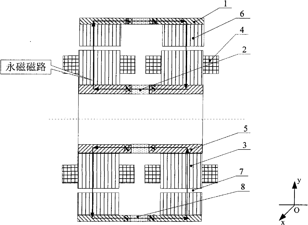
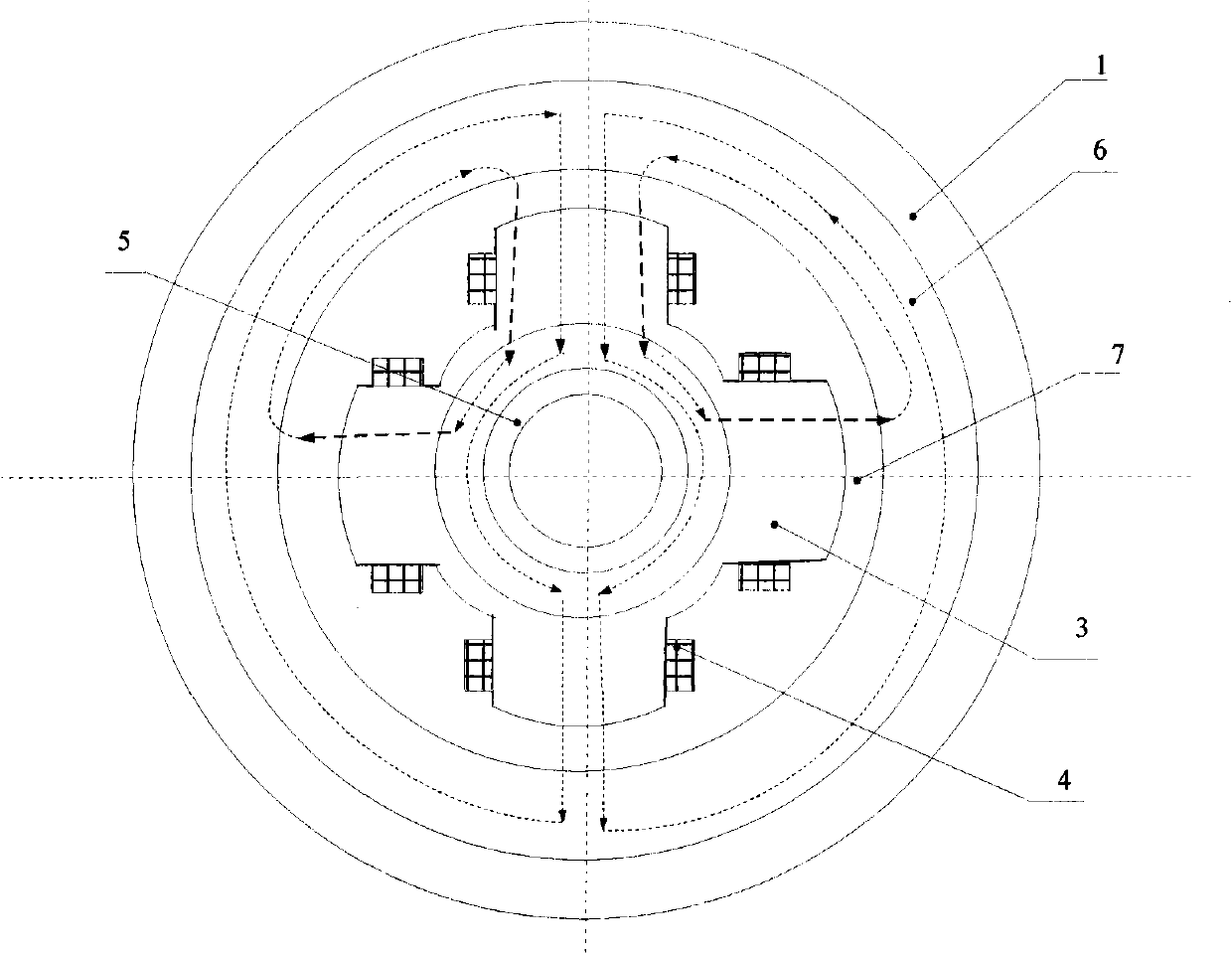
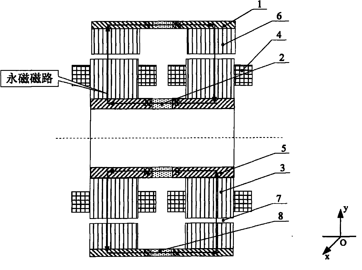
[0018] Such as figure 1 , 2 As shown, a dual permanent magnet external rotor permanent magnet bias radial magnetic bearing consists of an outer magnetic ring 1, an outer permanent magnet 8, a stator core 3, an excitation coil 4, an inner magnetic ring 5, an inner permanent magnet 2 and The rotor core is composed of 6, each stator core 3 is composed of 4 magnetic poles, and 2 stator cores 3 are composed of 8 magnetic poles at the left and right ends of the magnetic bearing, which respectively form the magnetic poles in the positive and negative directions of the X and Y axes. Each stator magnetic pole is wound with an excitation The coil 4, the rotor core 6 outside the stator core 3, the outer magnetic ring 1 outside the rotor core 6, the outer permanent magnet 8 is located between the two outer magnetic rings 1, the inner surface of the rotor core 6 and the outer surface of the stator core 3 remain There is a certain gap, forming an air gap 7 , the radial inner part of the st...


PUM


Abstract

The invention relates a double-permanent magnet outer-rotor permanent magnet biased radial magnetic bearing comprising outer magnetic conductive rings, outer permanent magnets, stator cores, excitation windings, inner magnetic conductive rings, inner permanent magnets and rotor cores, wherein four magnetic poles consist of each stator core, eight magnetic poles of the left end and the right end of the magnetic bearing consist of two stator cores, and magnetic poles in the positive and the negative directions of an X axis and a Y axis respectively consist of the eight magnetic poles; each stator magnetic pole is wound with the excitation winding; the rotor cores are positioned outside the stator cores; the outer magnetic conductive rings are positioned outside the rotor cores; the outer permanent magnets are positioned among the outer magnetic conductive rings; the outer magnetic conductive rings are connected with the rotor cores; certain gaps are retained on the inner surfaces of the rotor cores and the outer surfaces of the stator cores to form air gaps; and the permanent magnets are positioned among the inner magnetic conductive rings. The invention solves the problem of large remanence moment of the traditional permanent magnet biased outer-rotor radial magnetic bearing for space.

Description


Claims


Application Information

Patent Timeline
Owner BEIHANG UNIV
Why Eureka
Try Eureka