Inner rotor permanent magnet biased radial magnetic bearing with double permanent magnets

A permanent magnet bias, double permanent magnet technology, applied in the directions of bearings, shafts and bearings, mechanical equipment, etc., can solve the problems of large residual magnetic moment in the axial direction, increase the size of the device, and complex compensation methods, so as to reduce the residual magnetism. Moment, complex overcoming method, simple and reliable installation

Inactive Publication Date: 2014-04-23
BEIHANG UNIV
View PDF5 Cites 0 Cited by
  • Summary
  • Abstract
  • Description
  • Claims
  • Application Information

AI Technical Summary

Problems solved by technology

There are few existing methods for compensating the residual magnetic moment. The main method is to measure the residual magnetic moment through experiments, and to perform magnetic compensation through the magnetic torque device in the flywheel according to the magnetic conditions in the track. This method is very complicated to implement. Another method is to compensate by adding a permanent magnet. This method is still based on the experimental test, and the compensation of the external permanent magnet is carried out according to the measured results. The size of the permanent magnet added by this method has no rules to follow. Moreover, the external permanent magnet increases the volume of the flywheel and other devices, and the external permanent magnet brings unpredictable loss to the magnetically conductive rotating part of the flywheel and other devices at high speed, which affects the stability of the magnetic performance of the whole machine.
In view of the above reasons, the existing radial magnetic bearings have defects such as large residual magnetic moment in the axial direction and the existing compensation method is very complicated and will increase the volume of the device.

Method used


Image

  • Inner rotor permanent magnet biased radial magnetic bearing with double permanent magnets
  • Inner rotor permanent magnet biased radial magnetic bearing with double permanent magnets
  • Inner rotor permanent magnet biased radial magnetic bearing with double permanent magnets

Examples


Embodiment Construction

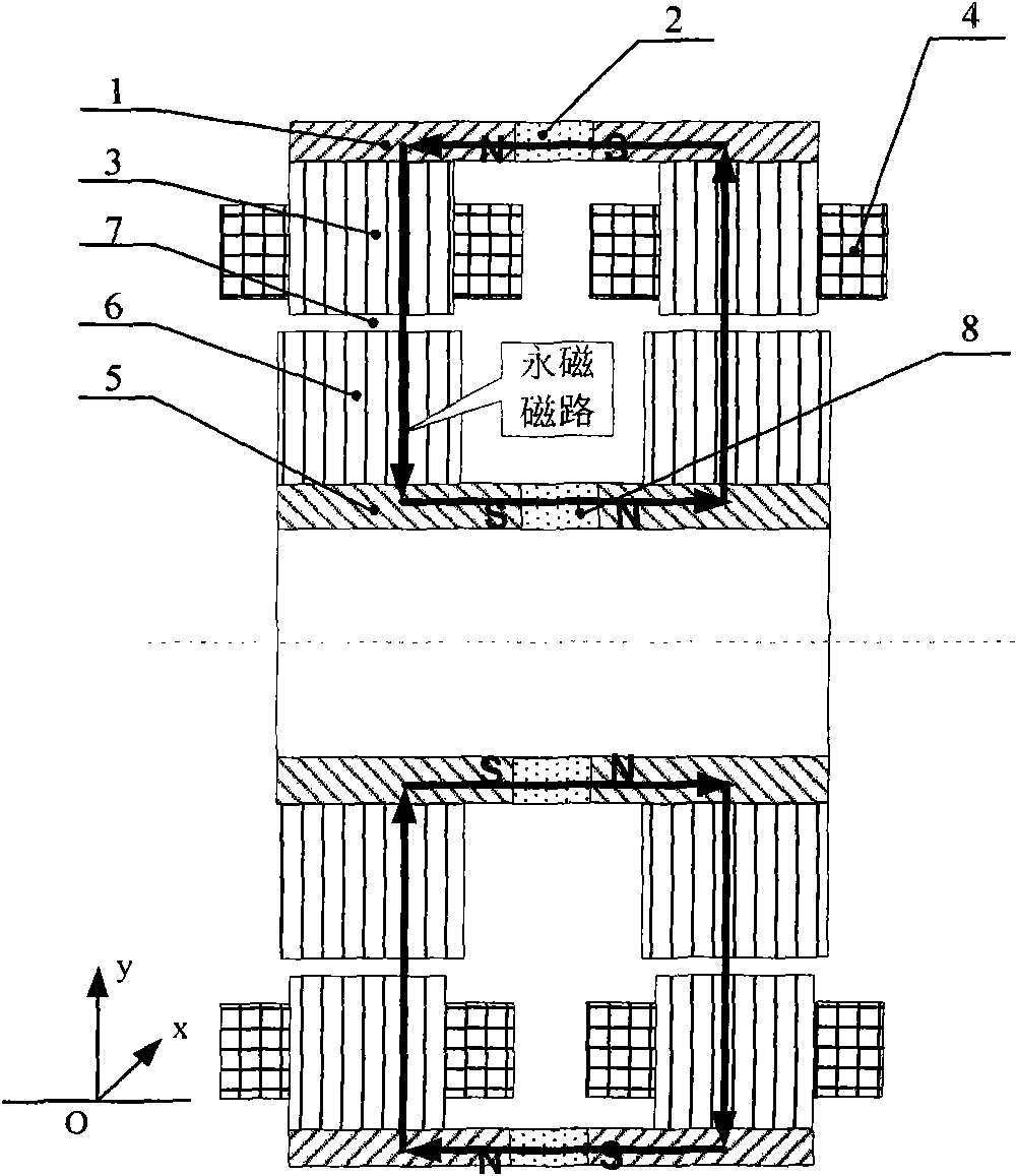
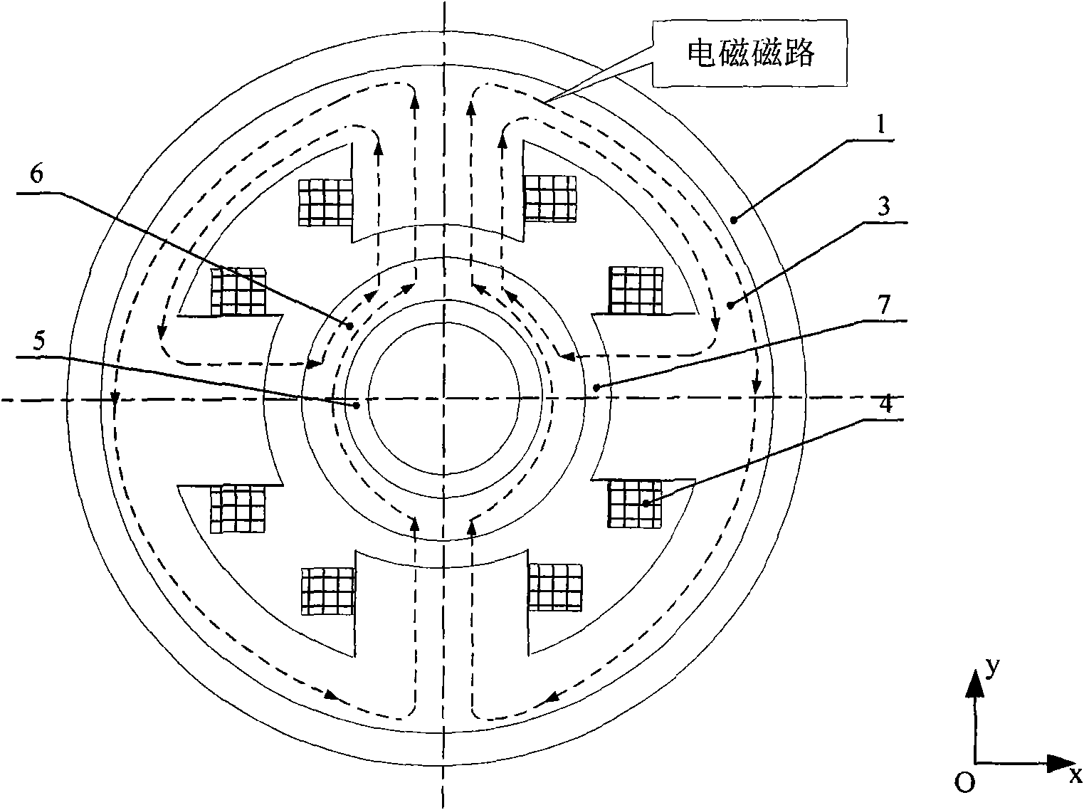
[0018] like figure 1 , 2 As shown, a radial magnetic bearing with double permanent magnet internal rotor permanent magnet bias is characterized in that: an outer magnetic ring 1, an outer permanent magnet 2, a stator core 3, an excitation coil 4, an inner magnetic ring 5, and a rotor Iron core 6 and inner permanent magnet 8, each stator core 3 forms 4 magnetic poles, and two stator cores 3 form 8 magnetic poles at the left and right ends of the magnetic bearing, which respectively form the magnetic poles in the positive and negative directions of the X and Y axes, and each stator magnetic pole The excitation coil 4 is wound, the outside of the stator core 3 is the outer magnetic ring 1, the outer permanent magnet 2 is located between the two outer magnetic rings 1, the inside of the stator core 3 is the rotor core 6, the inner surface of the stator core 3 and the rotor core 6 There is a certain gap on the outer surface to form an air gap 7. The inner magnetic ring 5 is instal...


PUM


Abstract

The invention relates to an inner rotor permanent magnet biased radial magnetic bearing with double permanent magnets, comprising outer magnetic rings, an outer permanent magnet, stator iron cores, exciting coils, rotor iron cores, inner magnetic rings and an inner permanent magnet. Either stator iron core forms four magnetic poles, the two stator iron cores form eight magnetic poles at the left end and the right end of the magnetic bearing, i.e. respectively forming the magnetic poles of the X-axis and the Y-axis in the positive directions and the negative directions, either stator magnetic pole is wound by the exciting coil, the outer magnetic ring is arranged outside and connected with either stator iron core, the outer permanent magnet is arranged among the outer magnetic rings, the rotor iron core is arranged inside either stator iron core, a certain gap is formed between the inner surface of the stator iron core and the outer surface of the rotor iron core so as to form an air gap, the inner magnetic ring is mounted inside either rotor iron core, and the rotor iron core at the left end and the rotor iron core at the right end are connected by the inner magnetic rings between which the inner permanent magnet is arranged. The invention solves the problem of great residual magnetic moment of a traditional permanent magnet biased inner rotor radial magnetic bearing.

Description

technical field [0001] The invention relates to a non-contact magnetic suspension bearing, in particular to a permanent magnet bias external rotor radial magnetic bearing for compensating residual magnetic moment, which can be used as a non-contact support for rotating components such as magnetic suspension control moment gyro and magnetic suspension flywheel system for space, Reduce the magnetic interference of its own residual magnetism to external components. Background technique [0002] Magnetic suspension bearings are divided into pure electromagnetic type and hybrid magnetic suspension bearing with permanent magnetic bias and electromagnetic control. The former uses large current and high power consumption, and the hybrid magnetic suspension bearing with permanent magnetic bias and electromagnetic control uses permanent magnets instead of pure electromagnetic magnetic bearings. The bias current in the bearing generates a bias magnetic field, the magnetic field generat...

Claims


Application Information

Patent Timeline
Patent Type & Authority Patents(China)
IPC IPC(8): F16C32/04
Inventor 孙津济房建成刘刚汤继强乐韵
Owner BEIHANG UNIV
Why Eureka
Try Eureka