Valve device for fuel tank and over-supply prevention device for fuel tank

A technology of fuel supply device and fuel tank, which is applied in the directions of liquid fuel feeder, arrangement combined with fuel supply of internal combustion engine, ventilation device, etc. Effect

Active Publication Date: 2014-10-08
NIFCO INC
View PDF8 Cites 0 Cited by
  • Summary
  • Abstract
  • Description
  • Claims
  • Application Information

AI Technical Summary

Problems solved by technology

However, in the device shown in Patent Document 1, since the through-hole is only provided on the housing, it is easy for the float valve to drop immediately after the full tank detection.
If the fuel level in the fuel supply pipe drops immediately after the full tank detection, the automatic stop of the lubricator will be released, and the fuel supply will be added immediately, resulting in excessive fuel supply.

Method used


Image

  • Valve device for fuel tank and over-supply prevention device for fuel tank
  • Valve device for fuel tank and over-supply prevention device for fuel tank
  • Valve device for fuel tank and over-supply prevention device for fuel tank

Examples


Embodiment Construction

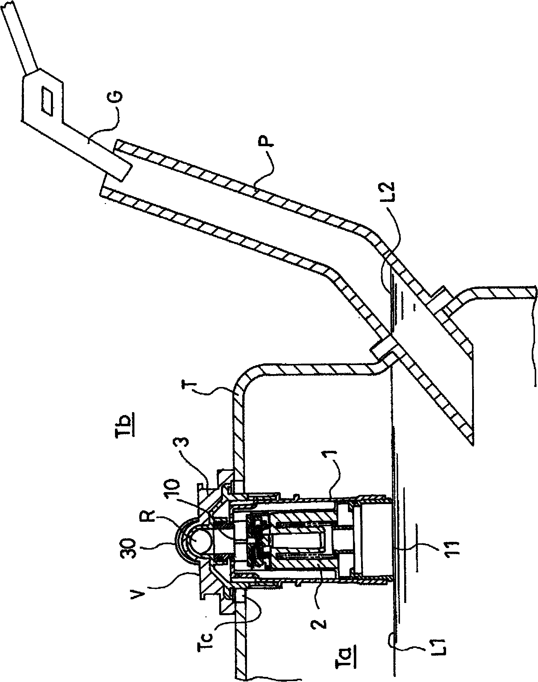
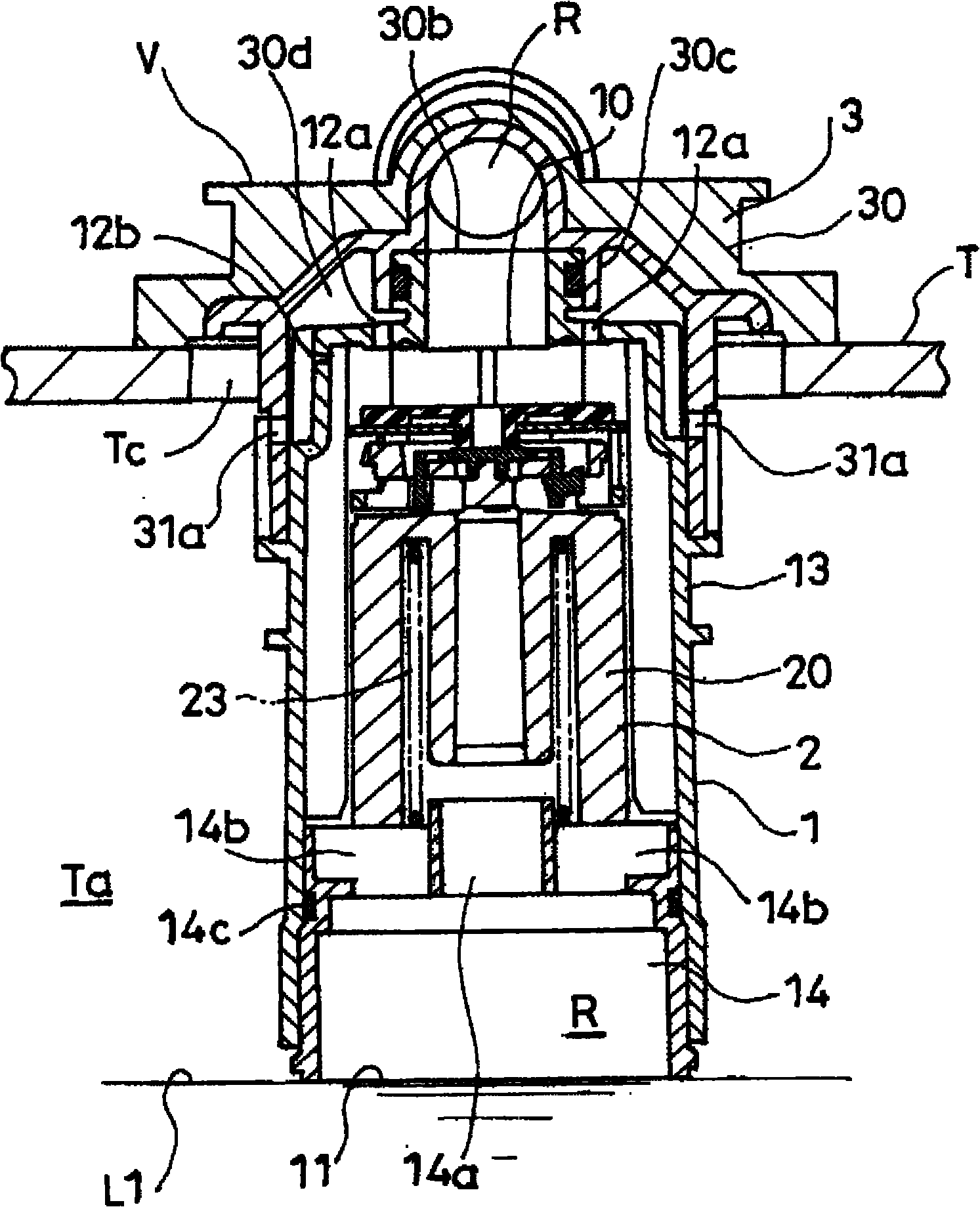
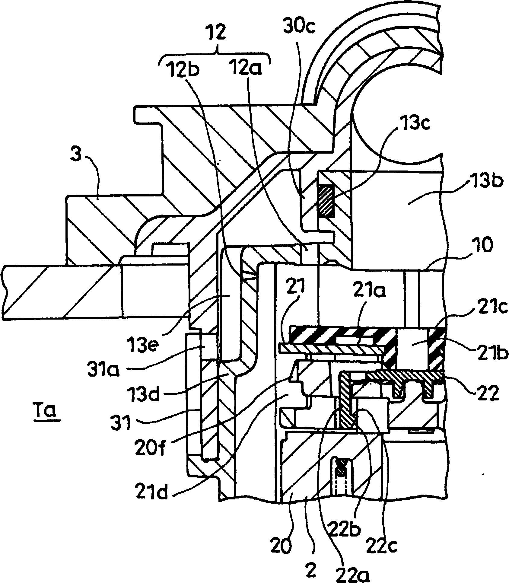
[0034] Below, according to Figure 1 to Figure 17 (b) describes the best mode for carrying out the present invention. and, Figure 1 to Figure 7 Showing the first example of the valve device V constructed by applying the present invention, Figure 8 A second example of the valve device V in which a part of the structure of the first example is changed, Figure 9 ~ Figure 12 (c) is a third example of the valve device V in which a part of the structure of the first example is changed, Figure 13 (a)(b) is a fourth example of the valve device V in which a part of the structure of the first example is changed, Figure 14 (a)(b) is a fifth example of the valve device V in which a part of the structure of the first example is changed, Figure 15 (a)(b) is a sixth example of the valve device V in which a part of the structure of the first example is changed, Figure 16 (a)(b) is a seventh example of the valve device V in which part of the structure of the first example is change...


PUM


Abstract

The present invention relates to a valve device for a fuel tank and an overfueling prevention device for a fuel tank. The valve device is installed on the fuel tank for use. It is equipped with: a casing, which is provided with a vent valve port communicating with the outside of the tank on the upper part, and has a fuel inflow part below the vent valve port; The fuel that flows into the casing through the inflow portion rises and sits on the vent valve port, and on the casing, at a position above the water line of the floating body when seated, there is formed a channel that communicates the inside of the tank with the inside of the casing. The ventilation portion, and the ventilation portion is reduced when the seat is seated.

Description

technical field [0001] The present invention relates to an improvement of a valve device mounted on a fuel tank of an automobile or a motorcycle and having a function of communicating the inside and outside of the fuel tank in an open state. Background technique [0002] As a valve device having a shut-off valve for a fuel tank and a full-tank detection mechanism, there is a technology disclosed in Patent Document 1. The device has an evaporation opening in the upper part of the housing housing the float valve and a fuel opening in the lower part. When the fuel level reaches the fuel opening due to fuel supply, the float valve rises to close the evaporation opening. As a result, the fuel level in the fuel supply pipe rises, the sensor of the fuel feeder detects that the tank is full, and the fuel supply is stopped. A through hole is provided on the upper part of the casing of the device. Once the fuel supply is stopped, the pressure in the casing and the pressure in the t...

Claims


Application Information

Patent Timeline
Patent Type & Authority Patents(China)
IPC IPC(8): B60K15/077B60K15/04F02M37/00
CPCY10T137/3099F02M37/0082B60K15/035F16K24/044B60K15/04B60K15/077F02M37/00
Inventor 广濑贵世本田逸雄渡边真三高井基治
Owner NIFCO INC
Why Eureka
Try Eureka