Obstacle detection method and system

An obstacle and obstacle sensor technology, applied in the field of detection, can solve problems such as increasing costs

Inactive Publication Date: 2011-04-20
CATERPILLAR INC
View PDF1 Cites 5 Cited by
  • Summary
  • Abstract
  • Description
  • Claims
  • Application Information

AI Technical Summary

Problems solved by technology

Since this weighting requires information about extrinsic parameters, additional hardware is required
Also, these additional hardware add to the cost of implementing the method

Method used


Image

  • Obstacle detection method and system
  • Obstacle detection method and system
  • Obstacle detection method and system

Examples


Embodiment Construction

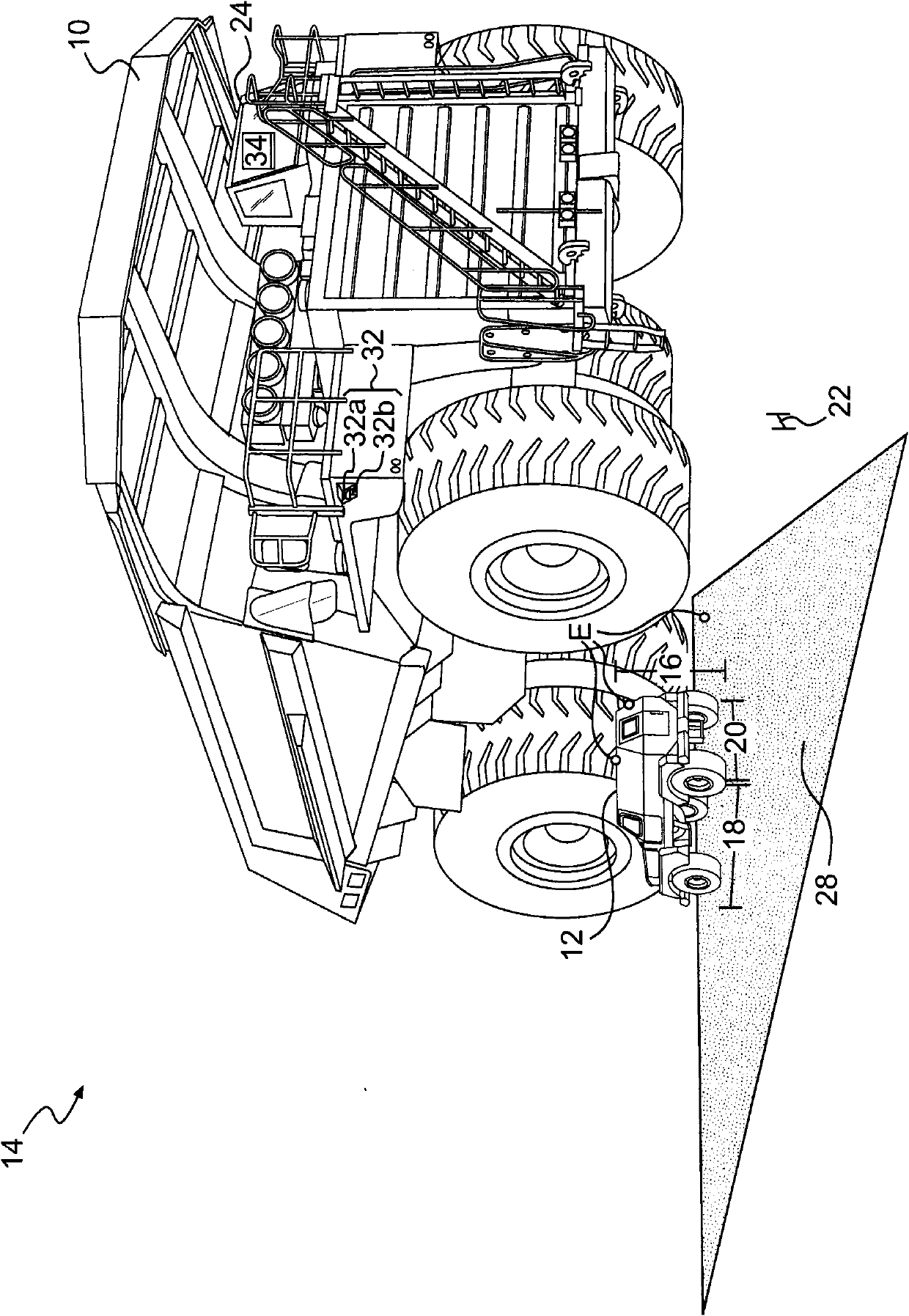
[0014] figure 1 An exemplary machine 10 and an obstacle 12 to the machine 10 are shown both at a worksite 14 . Although machine 10 is depicted as a non-highway haul truck, it is contemplated that machine 10 may embody other types of large machines such as wheel loaders, excavators, or motor graders. Barrier 12 is depicted as a service vehicle. However, it is contemplated that barrier 12 may embody other types of barriers, such as a pick-up truck or passenger vehicle. An obstacle 12 may be classified as hazardous if it is of at least a certain size. For example, the certain dimension may be a length 22 . An obstacle 12 may be classified as hazardous if its height 16 is greater than its length 22 , its width 18 is greater than its length 22 , or its depth 20 is greater than its length 22 . Worksite 14 may be, for example, a mine, landfill, quarry, construction site, or other type of worksite known in the art.

[0015] Machine 10 may have operator station 24 positioned to mi...


PUM


Abstract

A system (30) for detecting obstacles (12) near a machine (10) is disclosed. The system has a plurality of obstacle sensors (32) located on the machine. The system also has a controller (34) in communication with each of the plurality of obstacle sensors. The controller is configured to pair one-to-one each of the plurality of obstacle sensors to each of a plurality of non-overlapping confidence regions (44). Additionally, the controller is configured to scan with the plurality of obstacle sensors. The controller is also configured to receive from the plurality of obstacle sensors raw data regarding the scanning, and assemble the raw data into a map (36). Based on the map, the controller is configured to determine at least one characteristic of at least one obstacle.

Description

technical field [0001] The present invention relates generally to detection methods, and more particularly to a method for detecting obstacles in the vicinity of a machine. Background technique [0002] Large machines such as wheel loaders, off-highway haul trucks, excavators, motor graders, and other types of earth moving machines are used to perform a variety of tasks. Some of these tasks involve intermittently moving between and stopping at certain locations on the worksite, which may be difficult to complete safely and efficiently due to the poor visibility provided to the machine operator. Thus, the operator of the machine can additionally be provided with the detection of the obstacle sensor. However, each obstacle sensor operates effectively (ie, provides accurate detection) only within a certain spatial region. Outside these areas, obstacle sensors may provide inaccurate detections. For example, one obstacle sensor may detect an obstacle at a certain location, whi...

Claims


Application Information

Patent Timeline
Patent Type & Authority Applications(China)
IPC IPC(8): G01S17/89G01S17/93G01S13/931G01S17/931
CPCG01S17/936G01S13/87G08G1/16G01S2013/9332G01S13/931G01S7/4802G01S2013/9315G01S17/931
Inventor B·科特约施耶尔D·爱德华兹
Owner CATERPILLAR INC
Why Eureka
Try Eureka