Spiral load brake

A brake and screw technology, applied in the direction of brake type, automatic brake, mechanical equipment, etc., can solve the problems of large volume, high friction noise, complex structure, etc., and achieve the effect of overcoming the large volume, improving the service life, and overcoming the inconvenience of operation.

Inactive Publication Date: 2011-04-27
翟贵才
View PDF0 Cites 2 Cited by
  • Summary
  • Abstract
  • Description
  • Claims
  • Application Information

AI Technical Summary

Problems solved by technology

The first form is bulky, complex in structure, expensive, prone to failure, and can only be used in places where electric operations are performed, and cannot be used in places where there is no electricity and motorized operations, and the use places are limited; the second form is inconvenient to operate , especially in the lifting work, the load drop is difficult to control, prone to accidents, and has potential safety hazards; the third form of transmission efficiency is too low, such as a pair of ordinary gear transmission efficiency above 98%, but the self-locking worm transmission efficiency is not Therefore, the supporting power of the self-locking worm transmission is generally 2 times or more than the supporting power of the gear transmission with the same load; the fourth form is between the ratchet and the pawl, and between the ratchet and the friction plate and the transmission shaft. Dry friction occurs on the contact surface in the transmission, and the speed of the transmission shaft is limited. At present, it is only used in chain hoists and manual winches; if this form is directly applied to the transmission and manufacturing In the dynamic system, the relative speed between the ratchet and the pawl, between the ratchet and the friction plate and the transmission shaft is high, and the contact surface between the ratchet and the pawl, between the ratchet and the friction plate and the transmission shaft cannot be increased. Lubricant injection (lubricant injection will cause brake failure), will inevitably cause the contact surface between the ratchet and the pawl, and the ratchet and the transmission shaft to be worn quickly, resulting in damage to the braking system and making it unusable, and the ratchet, pawl The friction noise is large, so this form is not suitable for application in the transmission and braking systems of lifting and transport machinery driven by machines and electrics.

Method used


Image

  • Spiral load brake
  • Spiral load brake

Examples


Embodiment Construction

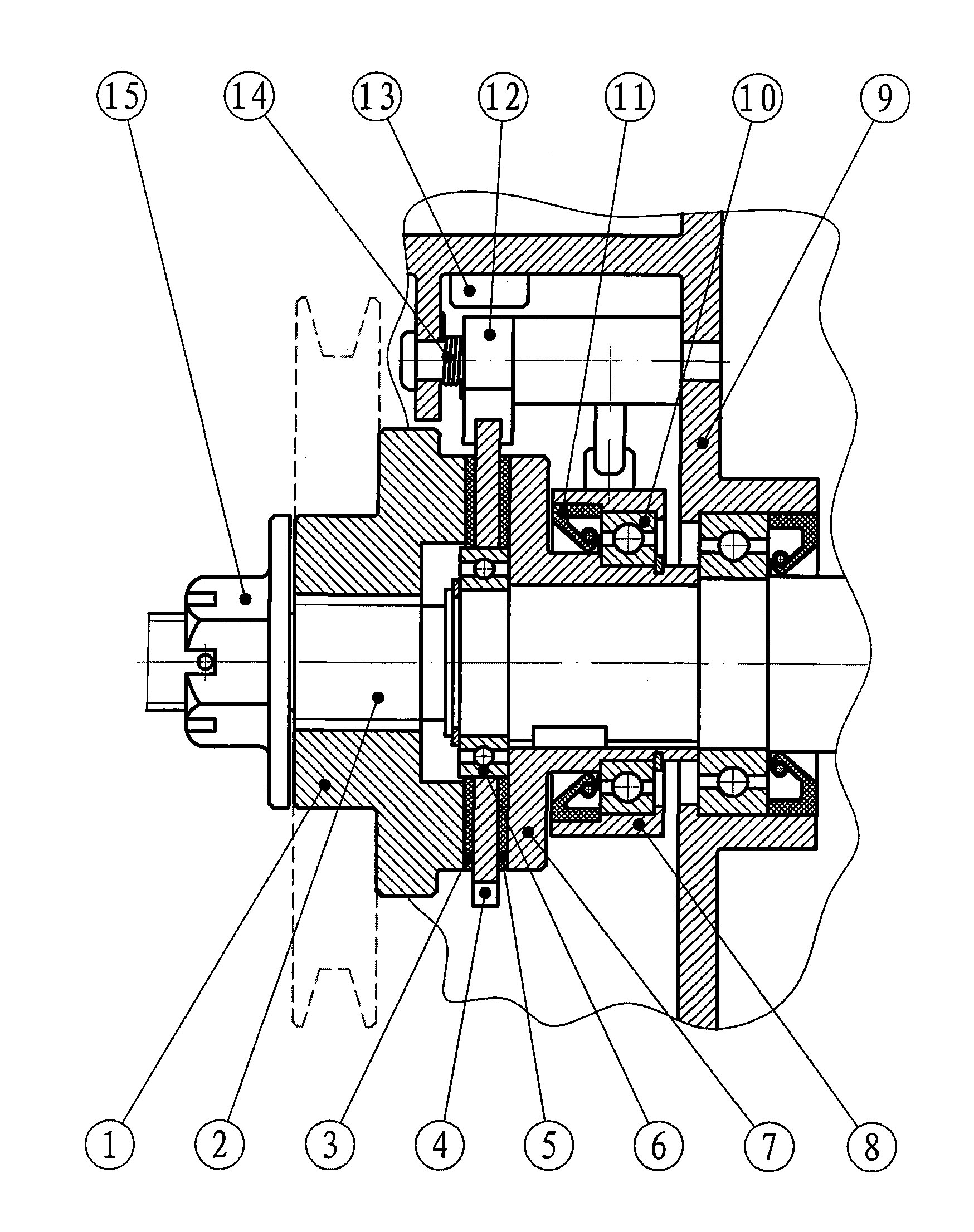
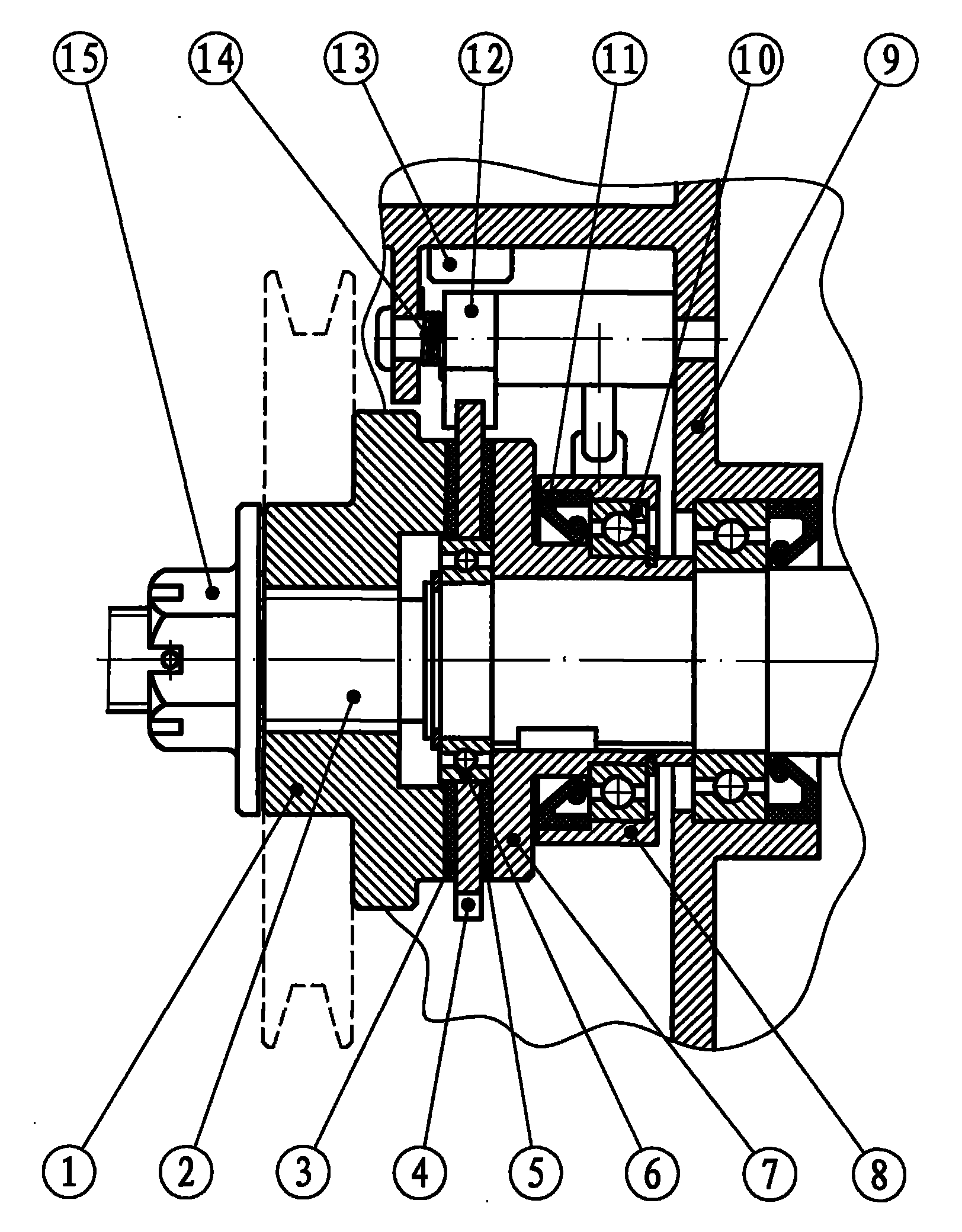
[0015] The present invention will be further described below in conjunction with the accompanying drawings and embodiments.

[0016]When the heavy object is lifted during the lifting work, the power drives the active friction disc 1 to rotate forward through the transmission wheel (the steering of the active friction disc 1 is set to forward rotation when the weight rises), and the active friction disc 1 moves axially and compresses instantly. Friction plate 3, ratchet 4, friction plate 5, driven friction disc 7, the pressing force is related to the size of the load, the greater the load, the greater the pressing force, the active friction disc 1 and friction plate 3, ratchet 4 , friction plate 5, driven friction disc 7, transmission shaft 2 are locked together and relatively static. At the same time, the dial 8 rotates with the transmission shaft 2 and the driven friction disc 7. Under the action of the friction force generated by the resistance ring 11, the ratchet 12 is dis...


PUM


Abstract

The invention discloses a spiral load brake and relates to the field of hoisting and transporting machines. The spiral load brake comprises a machine body, a driving friction disk, a transmission shaft, a ratchet wheel, a pawl, two friction plates, a driven friction disk, a bearing, a resistance ring, a thumb wheel, a pawl return spring, a pawl limiting seat and an adjusting nut. The driving friction disk is assembled on a multi-head external thread of the transmission shaft; the driven friction disk and the transmission shaft are connected together; the ratchet wheel is mounted on the transmission shaft and between the driving friction disk and the driven friction disk, a bearing is assembled between the ratchet wheel and the transmission shaft, and the ratchet wheel is free sheathed on a housing of the bearing;and the two friction plates are respectively arranged on two sides of the ratchet wheel between the driving friction disk and the driven friction disk; the pawl is hinged with the machine body; the thumb wheel is mounted on the transmission shaft through the bearing, the resistance ring and the driven friction disk; the pawl return spring is clamped on the pawl; the pawl limiting seat is mounted on the machine body; and the adjusting nut is mounted on one side on the transmission shaft in which the driving friction disk is located. The spiral load brake has the advantages of energy conservation, high efficiency, good braking property and safety in use, and can be widely applied in the hoisting and transporting machines.

Description

technical field [0001] The utility model relates to a helical load-bearing brake, which relates to hoisting and transportation machinery and is widely used in fields such as transmission and braking systems of hoisting and transportation machinery. Background technique [0002] At present, the domestic transmission and braking systems for lifting and transportation machinery adopt the following forms: one is that the transmission device without self-locking function is equipped with a motor with a brake or a matching electromagnetic brake; the other is that it does not have a self-locking function The transmission device is equipped with a manual brake; the third is a self-locking worm drive; the fourth is a screw brake for a chain hoist and a manual winch. The first form is bulky, complex in structure, expensive, prone to failure, and can only be used in places where electric operations are performed, and cannot be used in places where there is no electricity and motorized ...

Claims


Application Information

Patent Timeline
Patent Type & Authority Applications(China)
IPC IPC(8): F16D59/00
Inventor 翟贵才
Owner 翟贵才
Why Eureka
Try Eureka