
Lubricating wear state monitoring device and method for main bearing of diesel engine

A wear state and monitoring device technology, which is used in the installation and arrangement of acceleration sensors, ultrasonic sensors, and diesel engine main bearing lubrication and wear state monitoring devices. problems, to achieve high engineering application value, avoid dry friction, easy installation and operation

Inactive Publication Date: 2020-07-31
JIANGSU UNIV OF SCI & TECH
View PDF7 Cites 2 Cited by
  • Summary
  • Abstract
  • Description
  • Claims
  • Application Information

AI Technical Summary

Problems solved by technology

The disadvantage of this invention patent is that although the position of the faulty bearing can be found in the multi-speed main bearing and the degree of wear can be judged, the thermoelectric potential signal can only be read after the main bearing and the crankshaft come into contact, and the change of the minimum oil film thickness cannot be judged , the structure of the measuring device is complex, the installation process is cumbersome, and the applicability is poor

Method used


Image

  • Lubricating wear state monitoring device and method for main bearing of diesel engine
  • Lubricating wear state monitoring device and method for main bearing of diesel engine
  • Lubricating wear state monitoring device and method for main bearing of diesel engine

Examples


Embodiment Construction

[0041] In order to make the object, technical solution and advantages of the present invention clearer, the present invention will be further described in detail below in conjunction with the accompanying drawings and implementation examples. It should be understood that the specific implementation cases described here are only used to explain the present invention, not to limit the present invention.

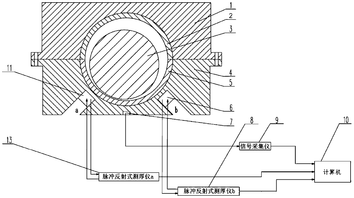
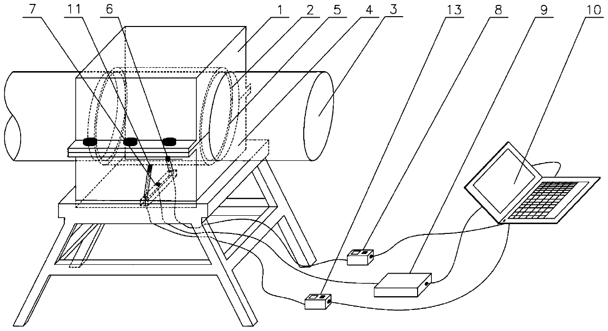
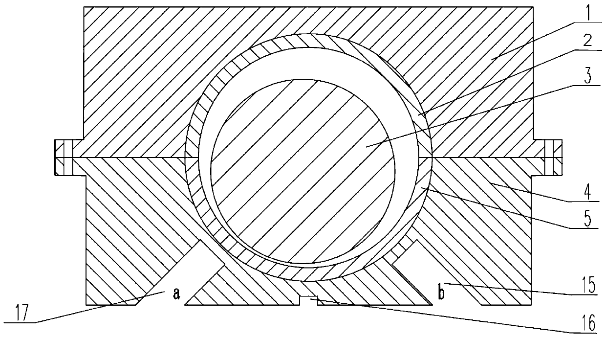
[0042] like figure 1As shown, it includes main bearing seat 1, upper bearing shell 2, crankshaft 3, main bearing cap 4, lower bearing shell 5, ultrasonic sensor probe b6, acceleration sensor 7, pulse reflection thickness gauge b8, signal acquisition instrument 9, computer 10, Ultrasonic sensor probe a11, pulse reflection thickness gauge a13.

[0043] The ultrasonic sensor probe a11 is sequentially connected to the pulse reflection type thickness gauge a13 and the computer 10 through wires; the ultrasonic sensor probe b6 is sequentially connected to the pulse reflection type th...


PUM

PropertyMeasurementUnit
Apertureaaaaaaaaaa
Hole depthaaaaaaaaaa

Abstract

The invention discloses a lubricating wear state monitoring device for a main bearing of a diesel engine. The device comprises an upper bearing bush, a lower bearing bush, a main bearing seat and a main bearing cover. A counter bore is formed in the center line of the main bearing cover, a blind hole a and a blind hole b are formed in the two sides of the center line at an included angle of 45 degrees respectively, and an ultrasonic sensor probe a is arranged in the blind hole a and sequentially connected with a pulse reflection type thickness gauge a and a computer through wires. An ultrasonic sensor probe b is arranged in the blind hole b. The ultrasonic sensor probe b is sequentially connected with a pulse reflection type thickness gauge b and a computer through wires. An acceleration sensor is arranged in the counter bore and is sequentially connected with a signal acquisition instrument and a computer through leads. The device is simple in structure and easy to install and operate. The lubricating state of the main bearing can be monitored in real time, the abrasion degree of the main bearing is obtained, safe operation of a diesel engine is guaranteed, and maintenance time and labor cost are saved.

Description

technical field [0001] The present invention relates to a diesel engine main bearing lubricating wear state monitoring device and method, in particular to the installation arrangement of an ultrasonic sensor and an acceleration sensor, which are used to detect the motion track of the crankshaft shaft center and the vibration of the main bearing cover, and then obtain the minimum oil film thickness of the main bearing, the bearing bush The wear depth and vibration characteristics belong to the technical field of diesel engine safety operation monitoring. Background technique [0002] For the main bearings of marine diesel engines, the traditional bearing wear detection method is to stop the machine and disassemble the bearings, and determine the bearing wear status through observation and measurement. However, marine diesel engines have high operating frequency, long intervals for regular shutdown and maintenance, and complicated disassembly. It is obviously difficult to meet...

Claims


Application Information

Patent Timeline
IPC IPC(8): G01B17/00G01B17/02G01M13/045
CPCG01B17/00G01B17/025G01M13/045
Inventor 朱军超钱海俣
Owner JIANGSU UNIV OF SCI & TECH
Learn More