Screw compressor

A technology for screw compressors and shells, which is applied in the direction of rotary piston machinery, mechanical equipment, machines/engines, etc., which can solve problems such as inability to supply oil, increased contact pressure, and mutual friction between metals, so as to reduce forced wear and prolong life , to avoid the effect of dry friction

Inactive Publication Date: 2004-07-07
LG ELECTRONICS (TIANJIN) APPLIANCES CO LTD
View PDF0 Cites 2 Cited by
  • Summary
  • Abstract
  • Description
  • Claims
  • Application Information

AI Technical Summary

Problems solved by technology

However, at the initial stage of starting, or when restarting after a certain period of time, the oil 18 at the bottom will be lifted to the upper part during the period of time due to the disappearance of the oil film inserted between the bearing 62 and the bottom surface of the movable scroll 32. Metal rubbing against each other
[0012] In addition, during operation, due to excessive compression, the contact pressure will increase on the insertion bearing surface 62 and the movable scroll 32, and the oil 18 cannot be fully supplied between the insertion bearing 62 and the bottom of the movable scroll 32.
This causes a phenomenon in which forced friction occurs between the insert bearing 62 and the bottom surface of the movable scroll 32

Method used


Image

  • Screw compressor
  • Screw compressor
  • Screw compressor

Examples


Embodiment Construction

[0024] Embodiments of the present invention are further described below in conjunction with the accompanying drawings:

[0025] In the figures described below, the parts having the same structures as those shown in the preceding figures are denoted by the same symbols for description.

[0026] As shown in the figure, the screw compressor consists of the following parts:

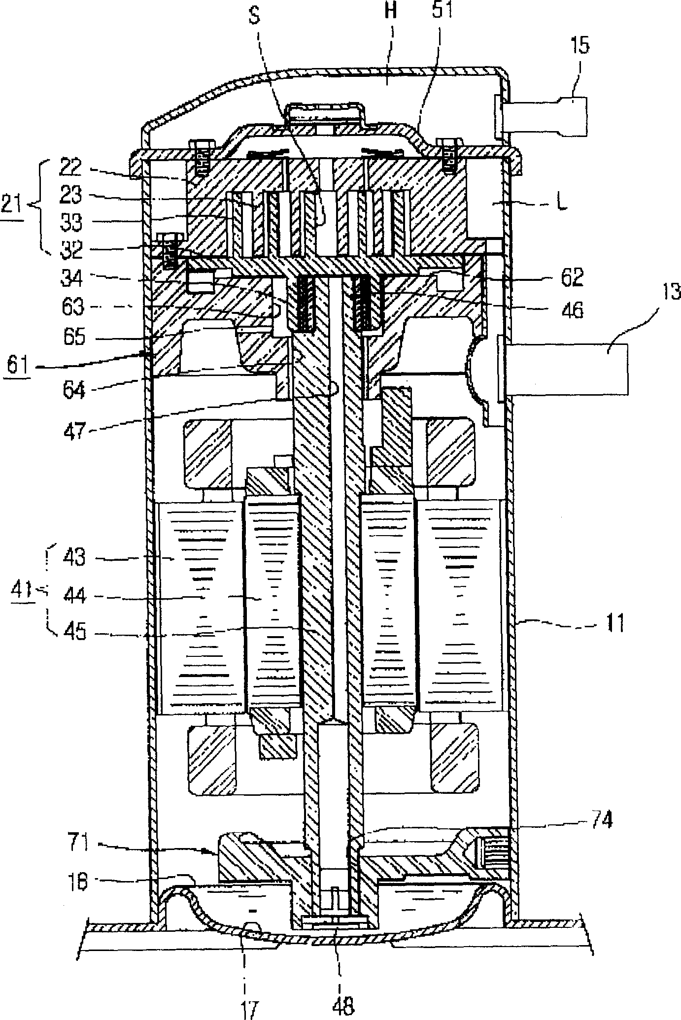
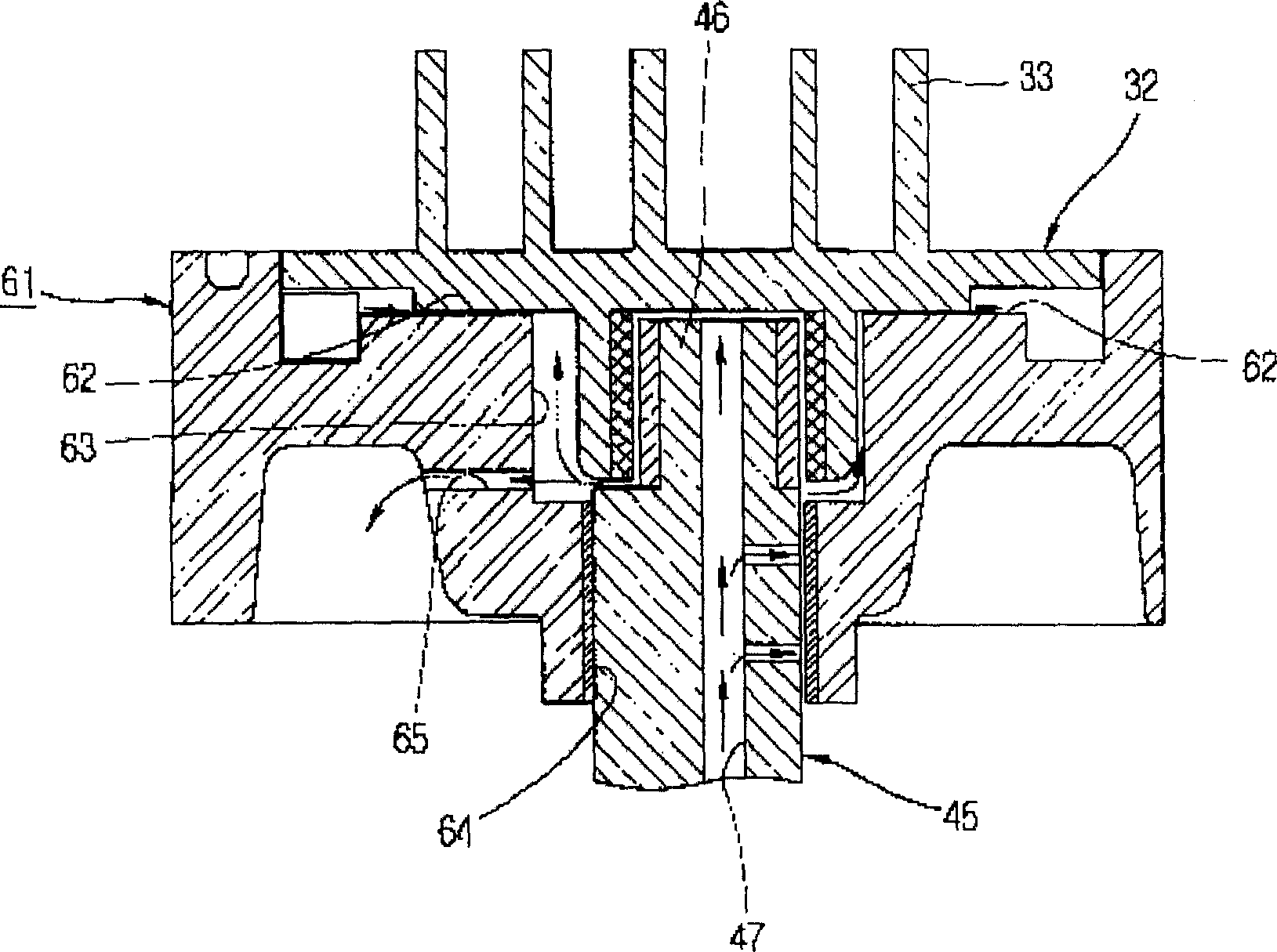
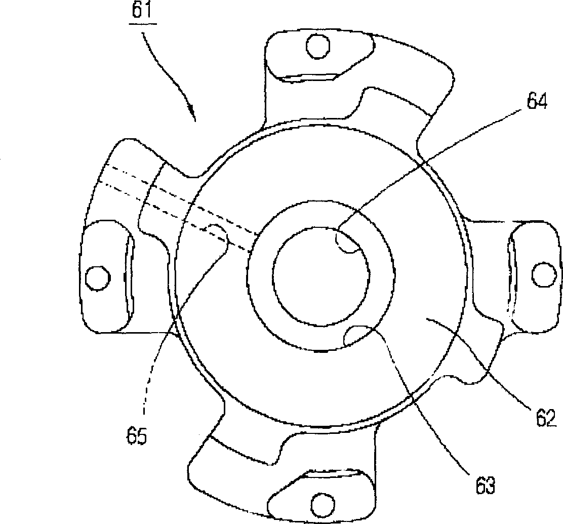
[0027] The present invention is a kind of screw type compressor, and its structure comprises the casing 11 that its inside forms sealed space; The refrigerant compression space has an involute shape rotating wing 33, and the movable scroll 32 that rotates with the fixed scroll 22; the main frame 61 that supports the movable scroll 32 to perform eccentric movement and contacts with its bottom surface forms a bearing surface 62, at least On one of the bottom surface of the orbiting scroll 32 and the insertion bearing surface 62 , there is an oil storage portion 81 that is recessed along the axial direction of ...


PUM


Abstract

A helical-lobe compressor is composed of a sealed casing, a static vortex disk with fixed involute wing, a moving vortex disk with rotary involute wing, and a main frame for supporting the moving vortex disk to do eccentrical movement and contacting with its bottom surface to form a bearing inserting surface. At least one of said bottom surface of moving vortex disk and said bearing inserting surface has an internal oil recepting part for preventing the dry friction between metallic parts.

Description

technical field [0001] The invention relates to a screw compressor, in particular to a screw compressor with an improved oil supply structure for the contact part between the main frame and the movable scroll in order to prevent friction between metals. Background technique [0002] As shown in the figure, the screw compressor has the following parts. It includes a casing 11 forming a sealed space inside, a compression part 21 located in the upper part of the casing 11 and compressing refrigerant, and a motor part 41 located below the compression part 21 and providing driving force for the compression part 21. [0003] A suction pipe 13 capable of sucking refrigerant is provided on one side of the casing 11 , and a discharge pipe 15 capable of discharging compressed refrigerant is provided on the upper side of the suction pipe 13 . [0004] The compression unit 21 is composed of a fixed scroll 22 having an involute-shaped fixed vane 23 fixed thereto, and a movable scroll 32...

Claims


Application Information

Patent Timeline
Patent Type & Authority Applications(China)
IPC IPC(8): F04C18/02F04C29/02
Inventor 张舜载
Owner LG ELECTRONICS (TIANJIN) APPLIANCES CO LTD
Why Eureka
Try Eureka