Electromagnetic heating controller

A heating controller and electromagnetic technology, applied in the direction of induction heating control, induction heating, etc., can solve the problems of complex process, non-moisture-proof, low power, etc., and achieve the effect of simple production process, strong over-current capability, and slow aging speed

Active Publication Date: 2011-05-11
广东永尚节能科技有限公司
View PDF6 Cites 5 Cited by
  • Summary
  • Abstract
  • Description
  • Claims
  • Application Information

AI Technical Summary

Problems solved by technology

[0010] The purpose of the present invention is to provide an electromagnetic heating controller for the deficiencies of the prior art, which solves the problems of the existing electromagnet

Method used


Image

  • Electromagnetic heating controller
  • Electromagnetic heating controller
  • Electromagnetic heating controller

Examples


Embodiment Construction

[0026] The present invention will be further described below in conjunction with the accompanying drawings.

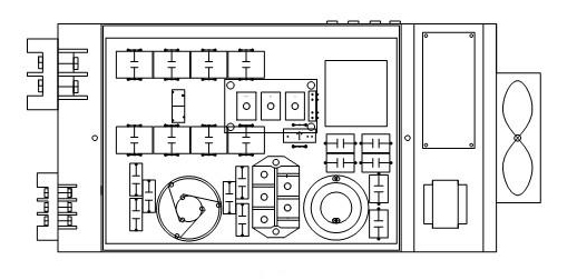
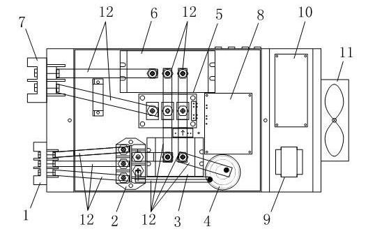
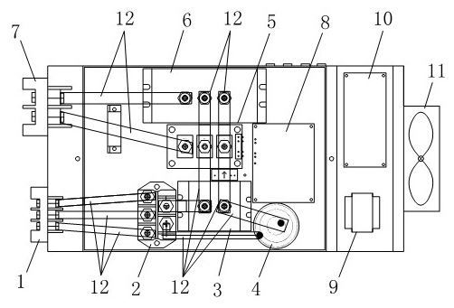
[0027] See figure 2 The electromagnetic heating controller circuit board of the present invention has a three-phase power input terminal 1, a three-phase rectification module 2, a filter capacitor 3, a filter inductor 4, an IGBT module 5, a resonant capacitor 6, a power output terminal 7, an IGBT drive circuit 8, Power transformer 9, control circuit 10, radiator 11, input transformer, output transformer, characterized in that: three-phase power input terminal 1, three-phase rectification module 2, filter capacitor 3, IGBT module 5, resonant capacitor 6, power supply The output terminal 7 is bridge-connected sequentially through the red copper strip 12, the filter inductor 4 is respectively bridge-connected to the three-phase rectifier module 2 and the filter capacitor 3 through the red copper strip 12, and the IGBT module 5 is connected to the power output terminal 7 ...


PUM


Abstract

The invention relates to the technical field of electromagnetic heating devices, in particular to an electromagnetic heating controller. The electromagnetic is characterized in that a circuit board is provided with a three-phase supply input terminal, a three-phase rectifying module, a filter capacitor, a filter inductor, an IGBT (insulated gate bipolar transistor) module, a resonant capacitor, a power output terminal, an IGBT driving circuit, a power transformer, a control circuit, a radiator, an input mutual inductor and an output mutual inductor; the three-phase supply input terminal, the three-phase rectifying module, the filter capacitor, the IGBT module, the resonant capacitor and the power output terminal are sequentially bridged and connected through red copper bars; the filter inductor is respectively bridged and connected with the three-phase rectifying module and the filter capacitor through red copper bars; and the IGBT module is bridged and connected with the power output terminal through a red copper bar. By adopting the red copper bar bridging scheme, the temperature is low; the temperature resistance is high, and the production process is simple; and the thickness and width of the copper bars for connecting the circuit have no limit, so the over current capability is strong, and the copper bars can be used for the electromagnetic heating controller with power of 8-30 KW, especially for the electromagnetic heating controller with power more than 30KW.

Description

[0001] technical field [0002] The invention relates to the technical field of electromagnetic heating devices, in particular to an electromagnetic heating controller. Background technique [0003] Electromagnetic heating equipment is an electrical appliance that uses the principle of electromagnetic induction to convert electrical energy into heat energy. Inside the electromagnetic equipment control core, the rectifier circuit converts the 50HZ / 60HZ alternating current into a DC voltage, and then the DC voltage is converted into a frequency by the control circuit. 20-40KHZ high-frequency voltage, the high-speed changing current passing through the coil will generate a high-speed changing magnetic field. When the magnetic force lines of the magnetic field pass through the metal, countless small eddy currents will be generated in the metal body, so that the heated object such as the barrel itself generates heat at a high speed. , so as to play a heating effect. figure 1 Sho...

Claims


Application Information

Patent Timeline
IPC IPC(8): H05B6/06
Inventor 梁斌勇胡海周胜袁光滔
Owner 广东永尚节能科技有限公司
Why Eureka
Try Eureka