Electronic equipment

A technology of electronic equipment and circuit boards, which is applied in the direction of circuits, electric switches, electrical components, etc., and can solve problems that affect the visual effect of the appearance and increase the difficulty of manufacturing and assembly

Inactive Publication Date: 2011-05-11
HONG FU JIN PRECISION IND (SHENZHEN) CO LTD +1
View PDF4 Cites 11 Cited by
  • Summary
  • Abstract
  • Description
  • Claims
  • Application Information

AI Technical Summary

Problems solved by technology

There are light-transmitting holes on the housing of electronic equipment, which affects the visual effect of its appearance and increases the difficulty of manufacturing and assembly

Method used


Image

  • Electronic equipment
  • Electronic equipment
  • Electronic equipment

Examples


Embodiment Construction

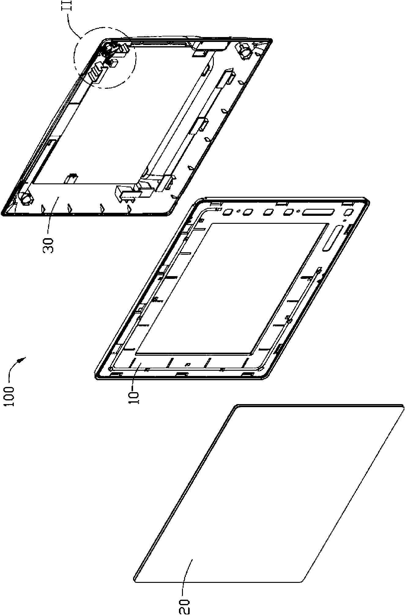
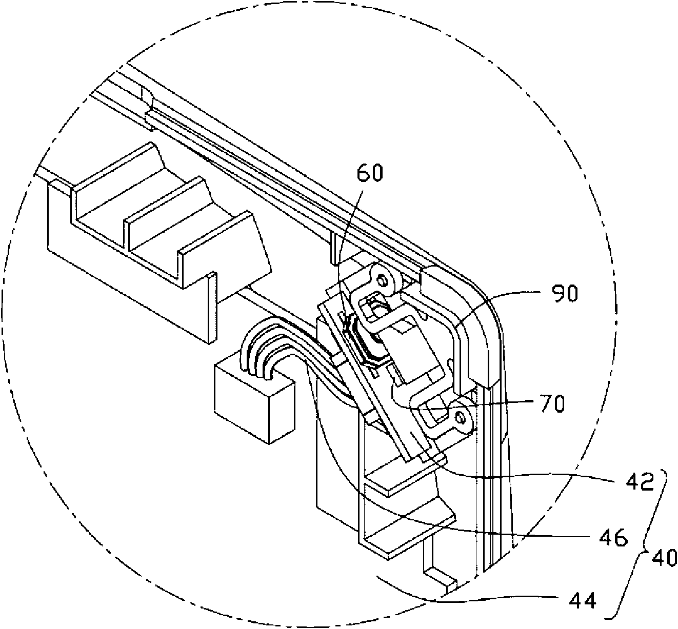
[0009] see figure 1 The electronic device 100 includes a frame body 10 , a panel 20 fixed on one side of the frame body 10 for displaying information, and a casing 30 fastened on the other side of the frame body 10 . Please also refer to figure 2 , the electronic device 100 further includes a circuit board module 40 , a trigger element 60 , a photosensitive element 70 and a button 90 . The circuit board module 40 is fixed on the casing 30 . The trigger element 60 and the photosensitive element 70 are carried on the 40 and electrically connected with the 40 . The button 90 is assembled on the housing 30 and movably abuts against the trigger 60 .

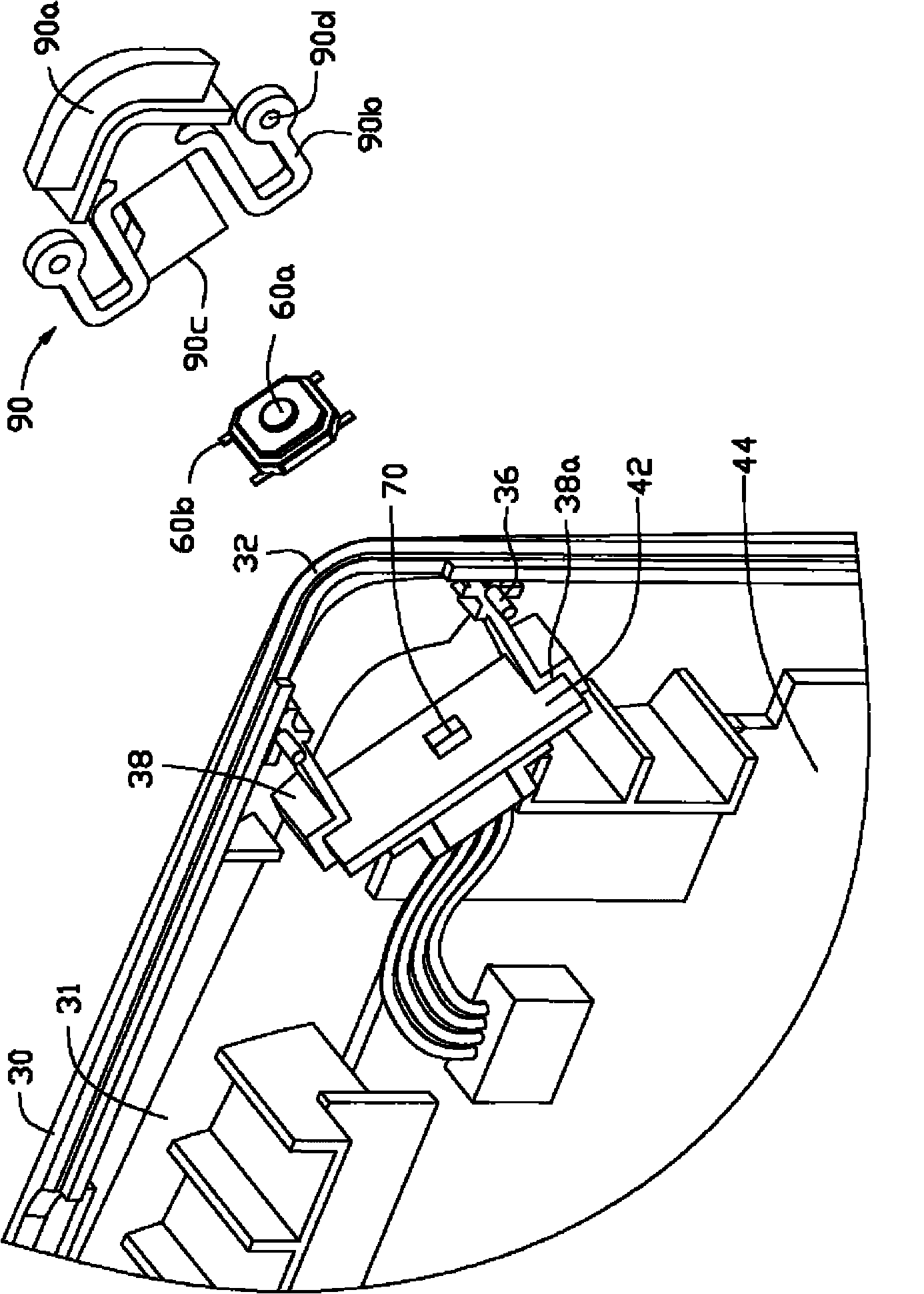
[0010] see image 3 , the casing 30 is formed with an accommodating cavity 31 for accommodating the circuit board module 40 . The circuit board module 40 includes a first circuit board 42 , a second circuit board 44 and a connector 46 connecting the first circuit board 42 and the second circuit board 44 . Both the trigger eleme...


PUM


Abstract

The invention provides electronic equipment which comprises a shell, a circuit board fixed in the shell, a photosensitive piece and a trigger piece and a key, wherein the photosensitive piece, the trigger piece and the key are fixed on the circuit board, the edge of the shell is provided with a key hole, the key is made of a transparent material and assembled on the shell by penetrating through the key hole and movably supports against the trigger piece; and the photosensitive piece senses outside light penetrating the key. The photosensitive piece senses the outside light through the key with the light transmission so as to automatically regulate the brightness of the electronic equipment. Compared with the mode that an opening is arranged on the shell for the photosensitive piece specially, the electronic equipment ensures that the shell is more attractive.

Description

technical field [0001] The invention relates to an electronic device. Background technique [0002] People expect to be able to use portable electronic devices such as digital photo frames and e-books under any lighting conditions, such as low light or too much light. For this reason, a light-transmitting hole is provided on the shell of the existing portable electronic device, and a photosensitive element is placed inside it. When the photosensitive element perceives changes in external light through the light-transmitting hole, the brightness of the display screen is automatically adjusted. Light-transmitting holes are provided on the housing of the electronic device, which affects the visual effect of its appearance and increases the difficulty of manufacturing and assembling. Contents of the invention [0003] In view of this, it is necessary to provide an electronic device in which the button and the photosensitive element are located at the same place. [0004] An ...

Claims


Application Information

Patent Timeline
Patent Type & Authority Applications(China)
IPC IPC(8): H05K5/02H01H13/14
CPCH01H13/52H01H2221/044H01H2221/07H03K17/968H03K2217/94106H05K5/02
Inventor 陈丙洲吴华锋
Owner HONG FU JIN PRECISION IND (SHENZHEN) CO LTD
Why Eureka
Try Eureka