Vibration device and electronic device

A technology of vibration devices and electronic equipment, applied in piezoelectric devices/electrostrictive devices, power oscillators, device material selection, etc.

Inactive Publication Date: 2011-05-18
SEIKO EPSON CORP
View PDF5 Cites 2 Cited by
  • Summary
  • Abstract
  • Description
  • Claims
  • Application Information

AI Technical Summary

Problems solved by technology

[0009] However, since the vibrating piece of Patent Document 2 has a structure in which the support portion protrudes laterally or laterally upward on both sides of the base, it is difficult to improve the Q value without increasing the size of the base including the support portion.

Method used


Image

  • Vibration device and electronic device
  • Vibration device and electronic device
  • Vibration device and electronic device

Examples


Embodiment approach

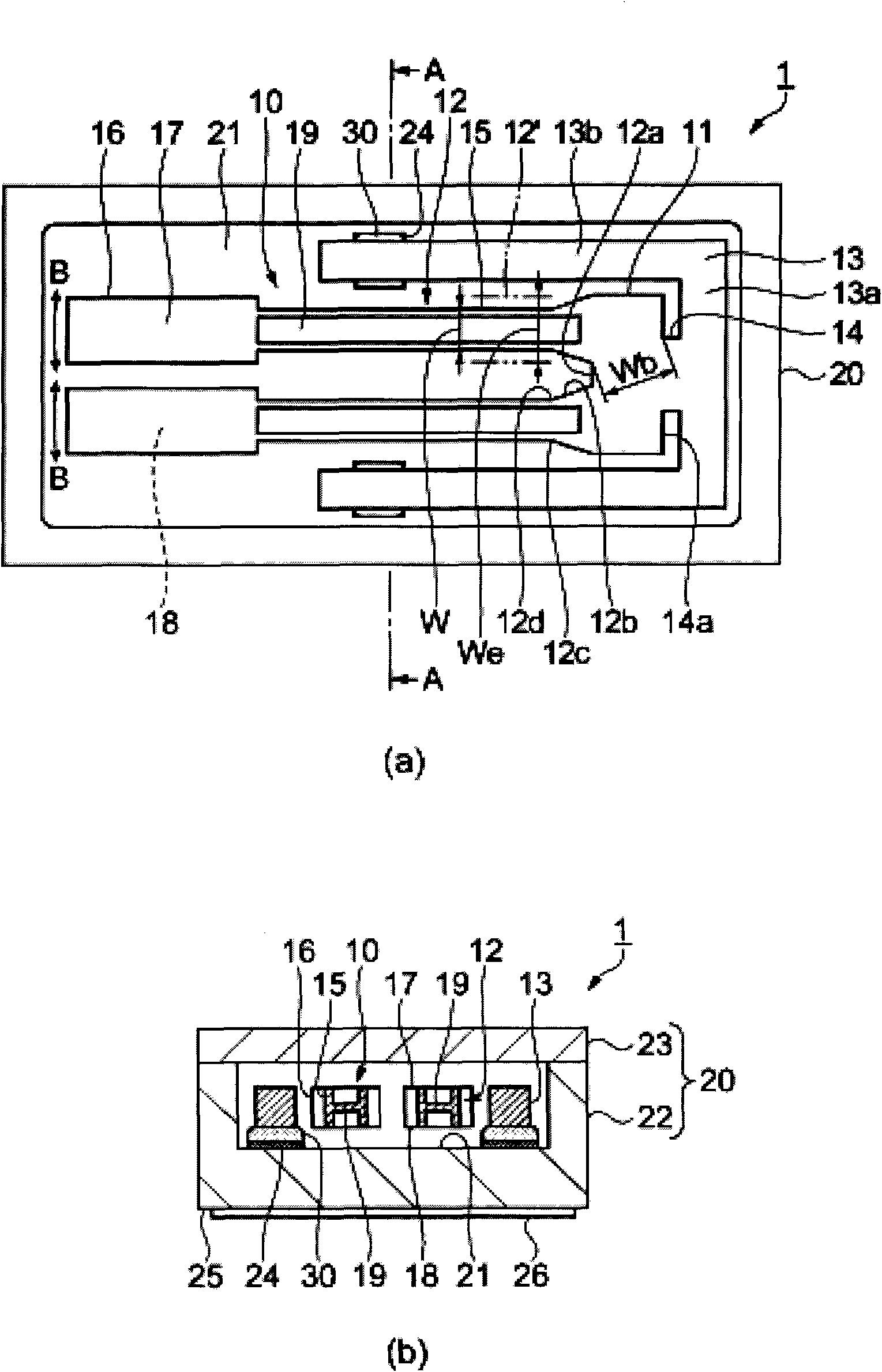
[0041] figure 1 is a schematic diagram showing a schematic structure of a quartz resonator as a vibration device. figure 1 (a) is a plan view viewed from the lid (lid body) side, figure 1 (b) is along figure 1 A cross-sectional view of line A-A in (a). In addition, in the top view, the cover is omitted for convenience.

[0042] like figure 1As shown, the crystal vibrator 1 has a tuning-fork-type crystal vibrating piece 10 as a vibrating piece that flexibly vibrates in the arrow B direction, and a package 20 that accommodates and fixes the quartz vibrating piece 10 therein.

[0043] The quartz vibrating piece 10 has: a base 11; a pair of vibrating arms 12 integrally formed with the base 11 and extending substantially parallel to each other from one end side of the base 11; 11 is connected to the other end side.

[0044] The base 11 of the quartz vibrating piece 10 has a width (orthogonal to the longitudinal direction of the vibrating arm 12) between one end side (the vibr...


PUM


Abstract

The invention provides a vibration device and an electronic device capable of increasing Q value. A quartz vibrating slice includes a base having a notch and a vibration arm including an arm section, a weight section and a groove section, wherein a mechanical resonant frequency f of the quartz vibrating slice is higher than a thermal relaxation frequency f0, and a closest approach distance between an outer edge of the notch and an outer edge of a crotch section formed between the vibrating arms is a base flexion width Wb, an arm width of the vibrating arm in a case of replacing a cross-sectional shape of the vibrating arm in a plane perpendicular to the longitudinal direction of the vibrating arm with a rectangular shape having a thermoelastic loss equivalent to a thermoelastic loss of the cross-sectional shape and a thickness equal to a thickness of the cross-sectional shape is an effective arm width We, a temperature difference caused in conjunction with a flexural vibration between the outer edge of the notch and the outer edge of the crotch section is d[Theta]b, and a temperature difference caused in conjunction with a flexural vibration between both ends of a root section of the vibrating arm in an arm width direction is d[Theta], the following relationship is satisfied, Wb>We*d[Theta]b / d[Theta] (where d[Theta]b

Description

technical field [0001] The present invention relates to a vibrating device having a vibrating piece for flexural vibration, electronic equipment and the like having the vibrating device. Background technique [0002] Patent Document 1 discloses a vibrating piece that has a base and a vibrating arm (hereinafter referred to as vibrating arm) protruding from the base, a groove is formed on the vibrating arm, and a cut-in is formed in the base. department. [0003] In addition, Patent Document 2 discloses a tuning fork-type vibrator (hereinafter referred to as a vibrating element) having a value-added portion (hereinafter referred to as a weighted portion) at the tip of a tuning fork formed in a U-shape or the like. And it has supporting parts protruding to the two outer sides of the tuning fork base or laterally upward. [0004] [Patent Document 1] Japanese Patent Laid-Open No. 2002-280870 [0005] [Patent Document 2] Japanese Publication No. 51-10755 [0006] In the vibrat...

Claims


Application Information

Patent Timeline
Patent Type & Authority Applications(China)
IPC IPC(8): H03H9/21
CPCH01L41/08H01L41/18H03H9/215H03B5/32H03H9/19H03H9/21H03H9/02H01L41/09H01L41/187H10N30/00H10N30/20H10N30/85H10N30/853
Inventor 山田明法
Owner SEIKO EPSON CORP
Why Eureka
Try Eureka