Optical transceiver

An optical transceiver and transceiver technology, applied in the field of optical communication, can solve problems such as occupying system resources and increasing costs, and achieve the effects of improving management functions, reducing network costs, and effective cost control

Active Publication Date: 2011-05-25
SOURCE PHOTONICS CHENGDU
View PDF4 Cites 2 Cited by
  • Summary
  • Abstract
  • Description
  • Claims
  • Application Information

AI Technical Summary

Problems solved by technology

[0005] Faced with this problem, the current existing solutions usually use a dedicated network management optical transceiver to realize t

Method used


Image

  • Optical transceiver
  • Optical transceiver
  • Optical transceiver

Examples


Embodiment Construction

[0034] All features disclosed in this specification, or steps in all methods or processes disclosed, may be combined in any manner, except for mutually exclusive features and / or steps.

[0035] Any feature disclosed in this specification (including any appended claims, abstract and drawings), unless expressly stated otherwise, may be replaced by alternative features which are equivalent or serve a similar purpose. That is, unless expressly stated otherwise, each feature is one example only of a series of equivalent or similar features.

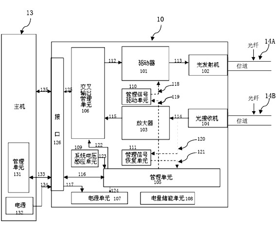
[0036] figure 1 It is a schematic diagram of the basic principles of the optical transceiver system of the present invention, which includes a host 13 and an optical transceiver 10; the host 13 includes a power supply 131 and a management unit 132; the optical transceiver 10 includes an interface 126, a cross output management unit 106, a driver 101, and a management signal drive unit 110, optical transmitter 102, optical receiver 104, amplif...


PUM


Abstract

The invention discloses an optical transceiver which comprises a management unit, a management signal driving unit, a crisscross output management unit, a driver, an optical transmitter, an optical receiver, an amplifier and a management signal recovery unit. The optical transceiver relies on the modulation way of the driver, thereby simply and effectively merging management signals with data signals; and the management signals are recovered at the receiving end of the optical transceiver through low-pass filtration and dynamic comparison way, compared with the existing scheme, the implementation way is more simple and high-efficient, and the cost control is more effective.

Description

technical field [0001] The present invention relates to the field of optical communication, in particular to an optical transceiver, which realizes the parallel transmission of data signals and management signals in optical fibers without affecting the transmission of data signals in optical fibers. With fiber link fault diagnosis function. Background technique [0002] With the rapid development of information technology, the data throughput is increasing, and corresponding network operators need to provide network equipment with greater data throughput and more effective data transmission methods. As the most efficient data transmission method at present, optical fiber communication is widely used in network data transmission. However, with the continuous development of information technology, the network structure tends to become larger and more complex. Therefore, in the face of a large and complex optical fiber data transmission network, how to Effective management and...

Claims


Application Information

Patent Timeline
IPC IPC(8): H04B10/12H04B10/08H04B10/40
Inventor 黄远军张盛忠周建华熊亚希
Owner SOURCE PHOTONICS CHENGDU
Why Eureka
Try Eureka