Coulomb friction damped disc brake caliper bracket

A technology of disc brakes and Coulomb friction, applied in the direction of brake types, brake components, and axial brakes, etc., can solve problems such as interface erosion

Inactive Publication Date: 2011-06-01
GM GLOBAL TECH OPERATIONS LLC
View PDF4 Cites 9 Cited by
  • Summary
  • Abstract
  • Description
  • Claims
  • Application Information

AI Technical Summary

Problems solved by technology

[0011] Although the aforementioned US Patent Application Publication US2007 / 0023240A1 solves the problem of brake squeal by using Coulomb friction, the problem that needs to be overcome is the problem of erosion at the interface of the two surfaces

Method used


Image

  • Coulomb friction damped disc brake caliper bracket
  • Coulomb friction damped disc brake caliper bracket
  • Coulomb friction damped disc brake caliper bracket

Examples


Embodiment Construction

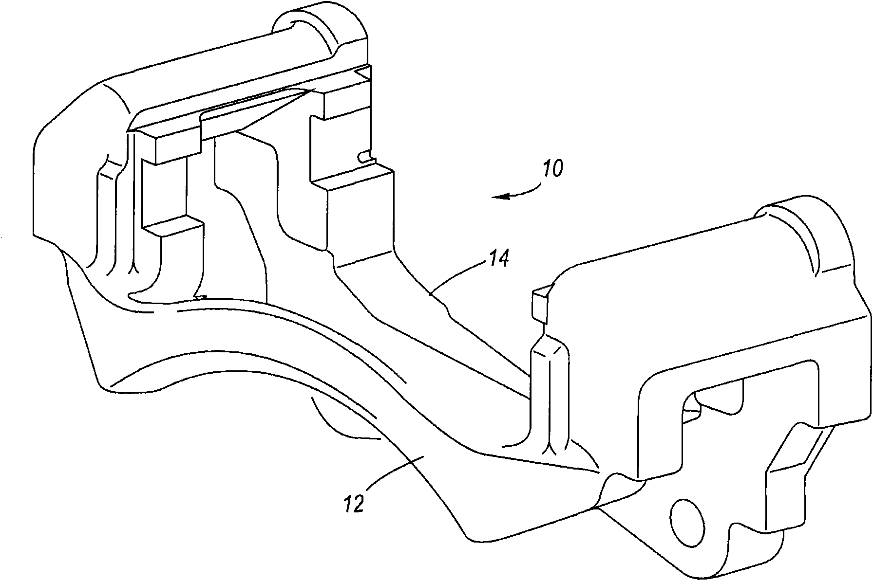
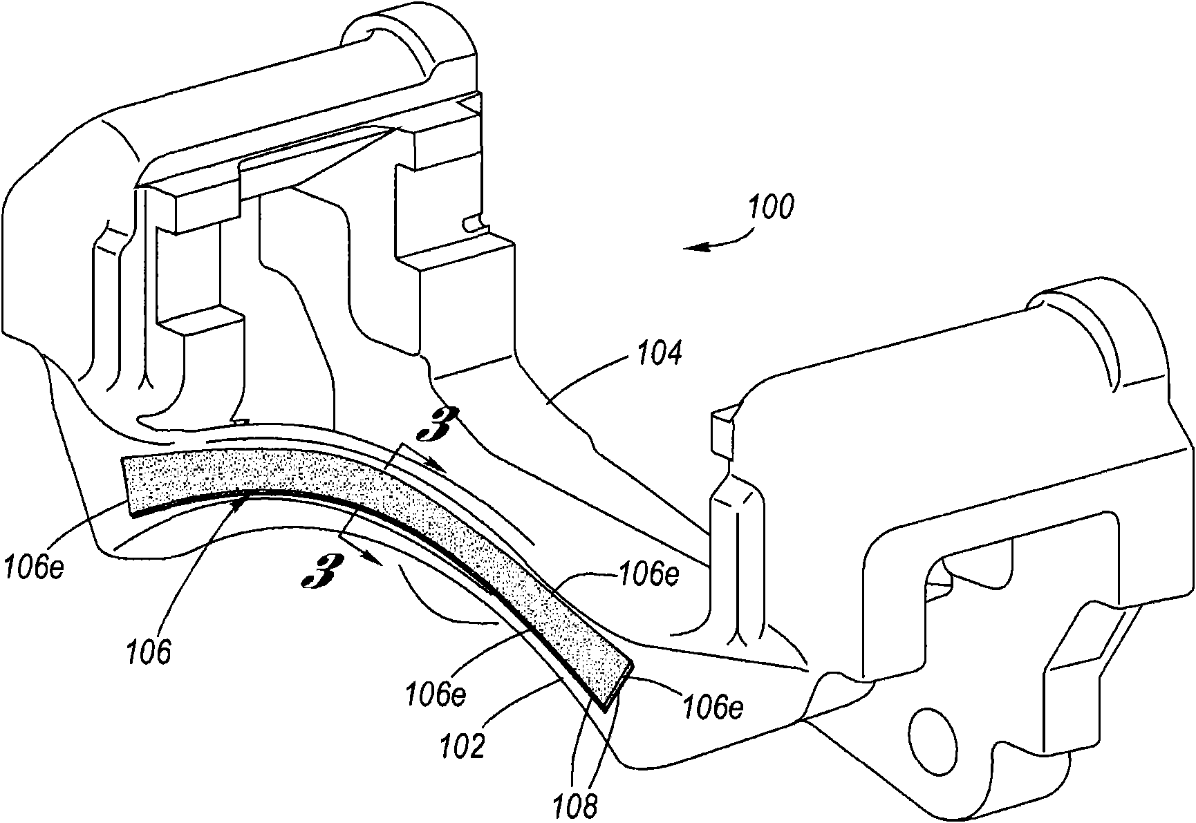
[0040] Referring now to the accompanying drawings, Figure 2 to Figure 5 Various aspects of an example of a disc brake caliper mount 100 for Coulomb friction damping for motor vehicle disc brake applications are shown.

[0041] In the disc brake calipers of the disc brake angle, figure 2 with image 3 A non-limiting example of a Coulomb friction damped disc brake caliper bracket 100 is shown, which can be used with the figure 2 The one shown is shaped differently, including an outer tie rod 102 and an inner tie rod 104 .

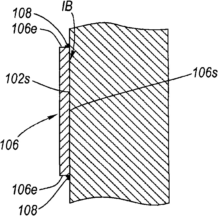
[0042] for in figure 2 In the example shown in , the Coulomb friction bar 106 is peripherally welded 108 to the outer surface 102s of the outer tie bar 102 . The term "peripheral welding" refers to the continuous welding of the Coulomb friction bar 106 to the outer surface 102s of the outer tie rod 102 as a closed loop or path along the peripheral edge 106e of the Coulomb friction bar 102 (see Figure 4 ), wherein the metal fusion caused by the perimete...


PUM


Abstract

A Coulomb friction damped disc brake caliper bracket, wherein damping is provided by Coulomb friction, most preferably at the outboard tie-bar thereof, by a Coulomb bar peripherally welded thereto. An inner surface of the Coulomb friction bar is in abutting contact with the external surface of the tie-bar, whereby because of the continuous peripheral edge welding, corrosion cannot find entry into the interface of the two surfaces, yet the two surfaces form are free to vibrate one as to the other in Coulomb friction fashion to thereby provide damping and reduction of brake squeal and other noise.

Description

technical field [0001] This invention relates to disc brake caliper mounts for use in automotive applications, and more particularly to Coulomb friction damped disc brake caliper mounts. Background technique [0002] The disc brake system of a motor vehicle uses a disc brake unit consisting of a disc brake rotor (disc brake disc) and a disc brake caliper at each respective wheel. [0003] Disc brake rotors generally include a rotor hat for attachment to an axle hub of a rotatable axle of a motor vehicle and at least one annular rotor hat connected to the rotor hat, wherein the at least one rotor hat has a Brake pads are selectively applied to opposing braking surfaces when braking is desired. In general, the rotor cheek configuration may be solid, in which case a single rotor cheek has opposing braking surfaces thereon, or the rotor cheek configuration may be open, in which case, A pair of rotor cheeks are spaced apart from each other by the webs of the ventilation vanes a...

Claims


Application Information

Patent Timeline
Patent Type & Authority Applications(China)
IPC IPC(8): F16D65/095
CPCF16D2055/0008F16D65/0006
Inventor B·D·洛M·T·里费O·S·德索基M·孙达尔C·N·杨
Owner GM GLOBAL TECH OPERATIONS LLC
Why Eureka
Try Eureka