Yarn tension device for a double-strand twisting spindle

一种纱线制动器、倍捻锭子的技术,应用在纺织品和造纸等方向,能够解决强纱线张力增加、纱线断裂等问题,达到高纱线张力的效果

Active Publication Date: 2011-06-22
SAURER TECH GMBH & CO KG
View PDF8 Cites 8 Cited by
  • Summary
  • Abstract
  • Description
  • Claims
  • Application Information

AI Technical Summary

Problems solved by technology

[0006] However, a disadvantage of this type of yarn brake is that the spring-loaded piston with the upper braking surface slides essentially without play in the axial guide of the yarn brake housing
In other words, the upper braking surface cannot move sideways, which causes yarn anomalies such as knots, thick spots, dust lumps, etc. to cause strong yarn tension increases, which in turn cause yarn breakage

Method used


Image

  • Yarn tension device for a double-strand twisting spindle
  • Yarn tension device for a double-strand twisting spindle
  • Yarn tension device for a double-strand twisting spindle

Examples


Embodiment Construction

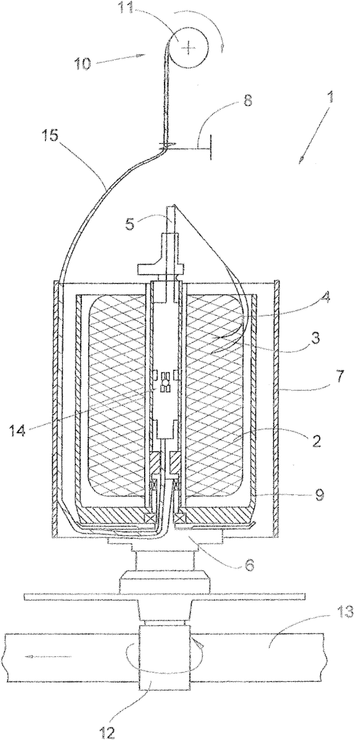
[0032] figure 1 The two-for-one twisting spindle, which is designated as a whole with the reference numeral 1 , is shown schematically in partial section. One or more yarns are arranged to be twisted by means of such two-for-one twisting spindles 1 . This twisting is provided to improve the quality of the yarn / counts, for example in terms of tear strength, and thus further improve the processability for subsequent processes such as weaving, weaving, knotting etc.

[0033] In this case the actual double twisting process is performed as follows:

[0034] like figure 1As shown in the embodiment of , the yarns 3 and 4 are for example unwound from a supply bobbin 2 mounted in a stationary protective tank 9 and introduced from above into the hollow shaft 5 of the two-for-one twisting spindle 1 . When passing through the hollow shaft 5, the yarns 3 and 4 are twisted by the rotatably mounted spindle part 6 (which is arranged below the protective tank 9), deflected in an L-shaped ma...


PUM


Abstract

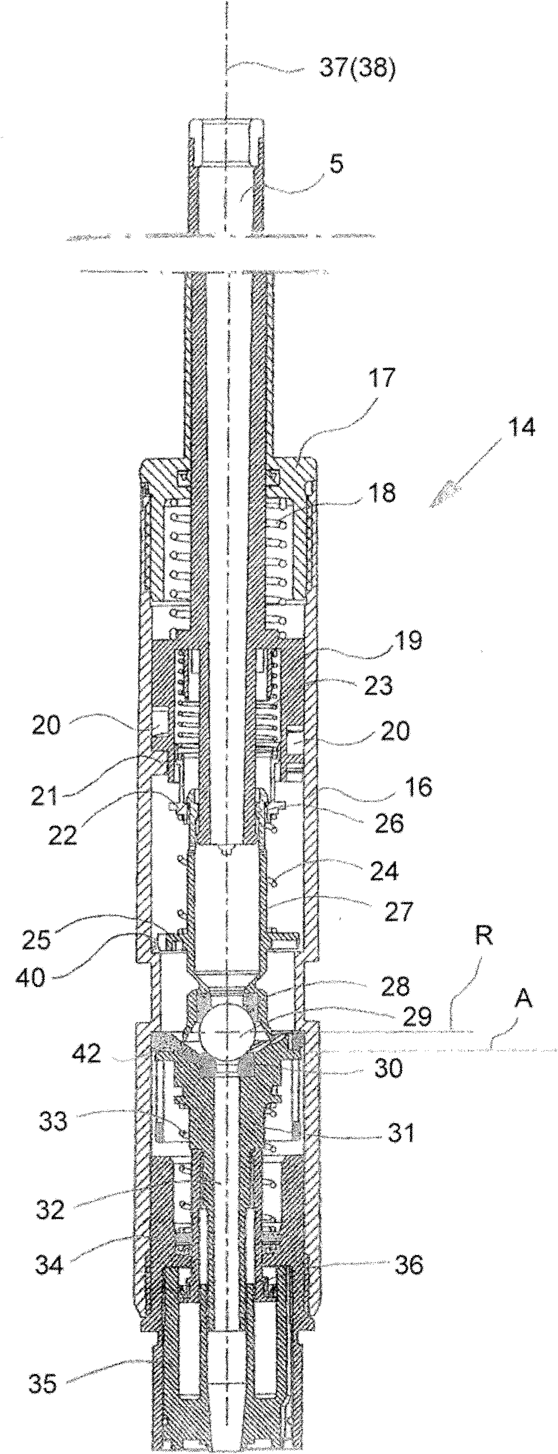
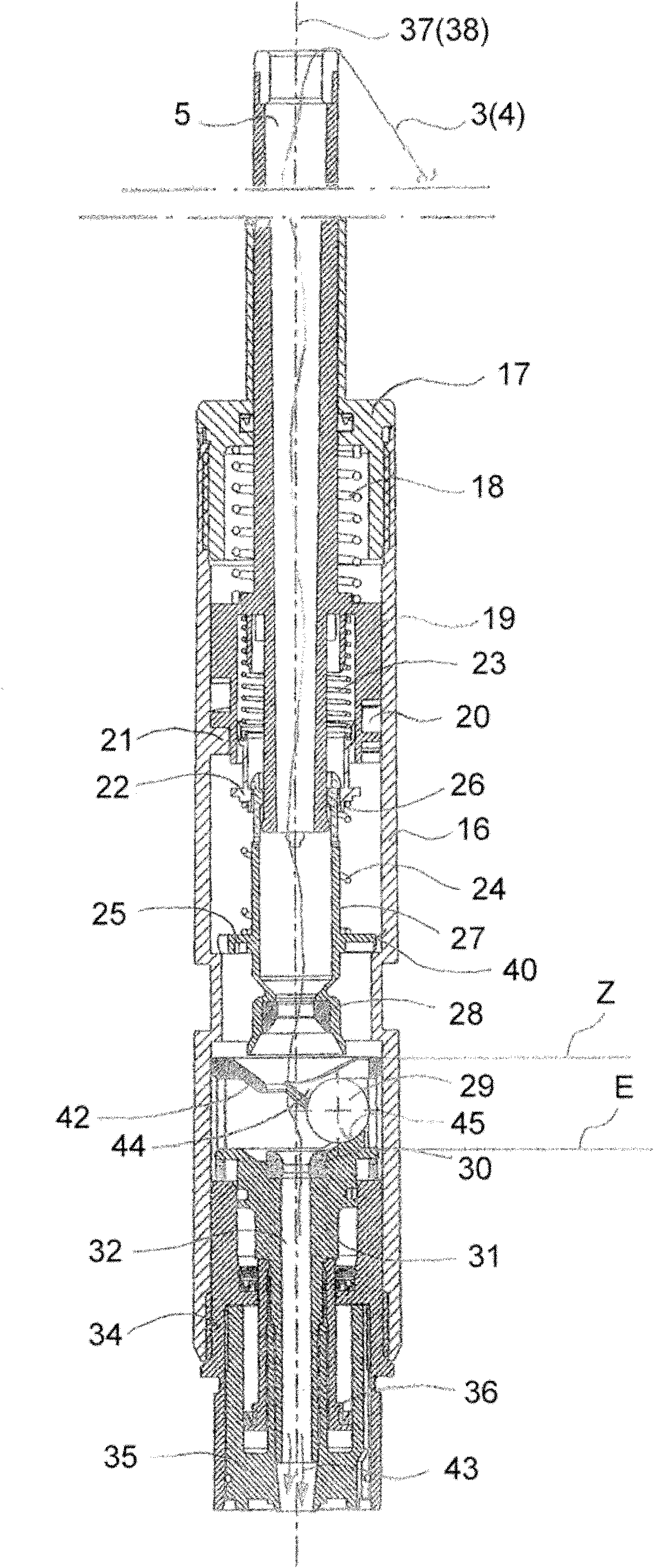
A yarn brake for a two-for-one twisting spindle has a brake element mounted in the region of a hollow axle of the spindle between an upper and a lower brake face, the braking force being predeterminable in a defined manner by means of the pretensioning of at least one spring element, which acts on an axially displaceably mounted upper piston, in which the upper brake face is integrated, and the yarn brake being pneumatically releasable to introduce a yarn. The upper piston (27) receiving the upper brake face (28) is configured in such a way and guided with play (S) within a housing (16) of the yarn brake (14) in such a way that it can move aside if necessary into a position (I), in which its center longitudinal axis (37) forms an angle ([alpha]) with the center longitudinal axis (38) of the housing (16).

Description

technical field [0001] The invention relates to a yarn brake for a two-for-one twisting spindle according to the preamble of claim 1 . Background technique [0002] Yarn brakes for two-for-one twisting spindles are already known in various configurations and are sometimes described in detail in numerous patents. Such yarn brakes are used in particular in two-for-one twisting processes and ensure that the yarn receives a specific pretension during the twisting process. [0003] A two-for-one twist spindle with a yarn brake configured as a brake cylinder is known, for example, from DE 31 39 236 C2. In a yarn brake of this type configured as a brake cylinder, two cylinders, pressed away from each other by means of spring elements and sliding telescopically within each other, support their spherical ends on a braking surface, which is arranged In the region of the yarn inlet or the yarn outlet of the brake housing, and in the process, the passing yarn is clamped. [0004] How...

Claims


Application Information

Patent Timeline
Patent Type & Authority Applications(China)
IPC IPC(8): D01H13/10
CPCD01H13/106
Inventor 约阿希姆·贝克斯马库斯·贝克曼因格·菲尔泽海因茨·芬克于尔根·施尼茨勒
Owner SAURER TECH GMBH & CO KG
Why Eureka
Try Eureka