Plate positioning device on bending machine

A technology of positioning device and bending machine, applied in the direction of positioning device, feeding device, storage device, etc., can solve the problems of difficult to overcome the impact of sheet metal, the influence of gear positioning accuracy, etc.

Active Publication Date: 2011-08-03
JIANGSU YAWEI MACHINE TOOL
View PDF7 Cites 10 Cited by
  • Summary
  • Abstract
  • Description
  • Claims
  • Application Information

AI Technical Summary

Problems solved by technology

However, this kind of finger is still difficult to overcome the impact of the sheet

Method used


Image

  • Plate positioning device on bending machine
  • Plate positioning device on bending machine
  • Plate positioning device on bending machine

Examples


Embodiment Construction

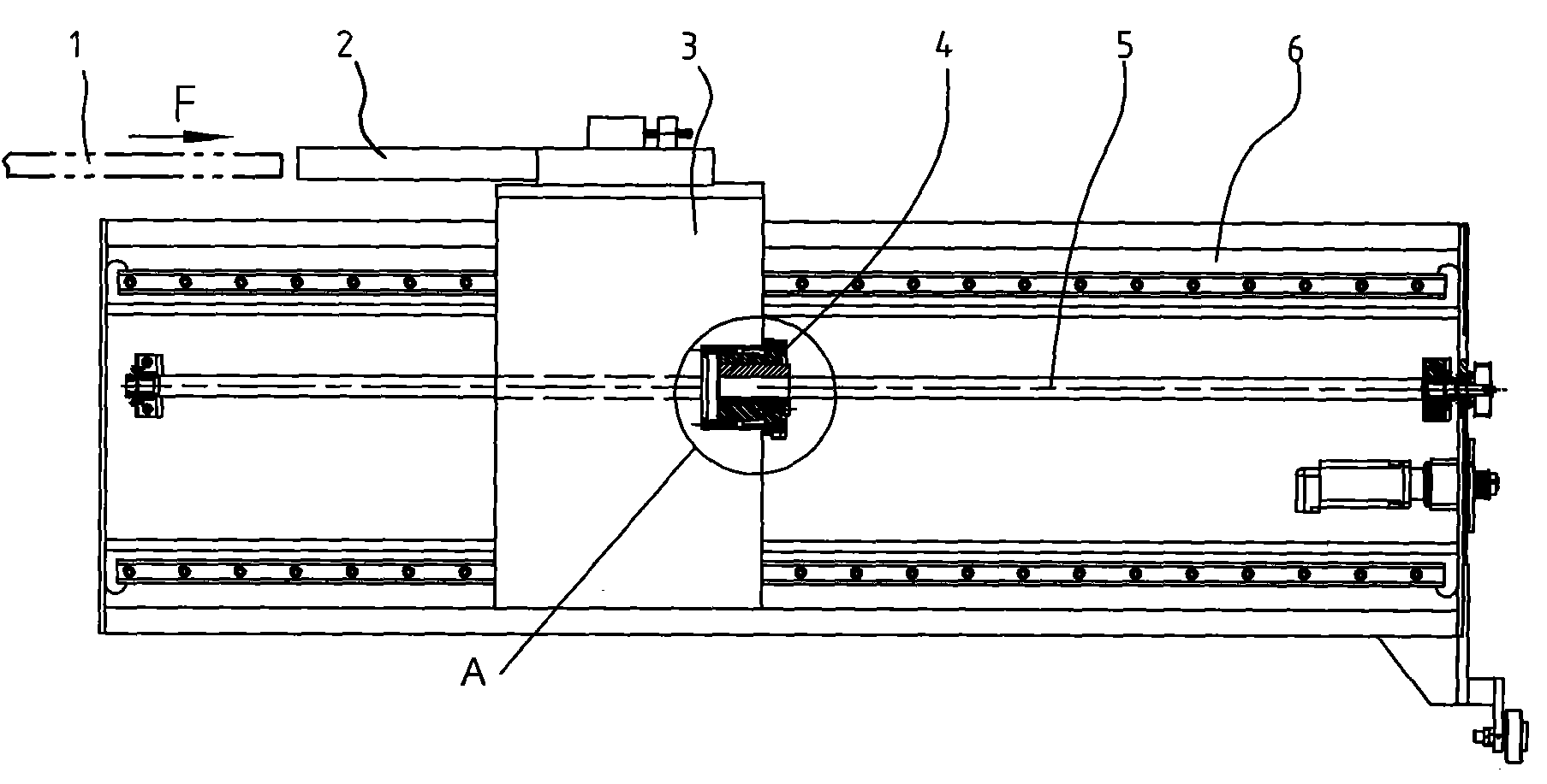
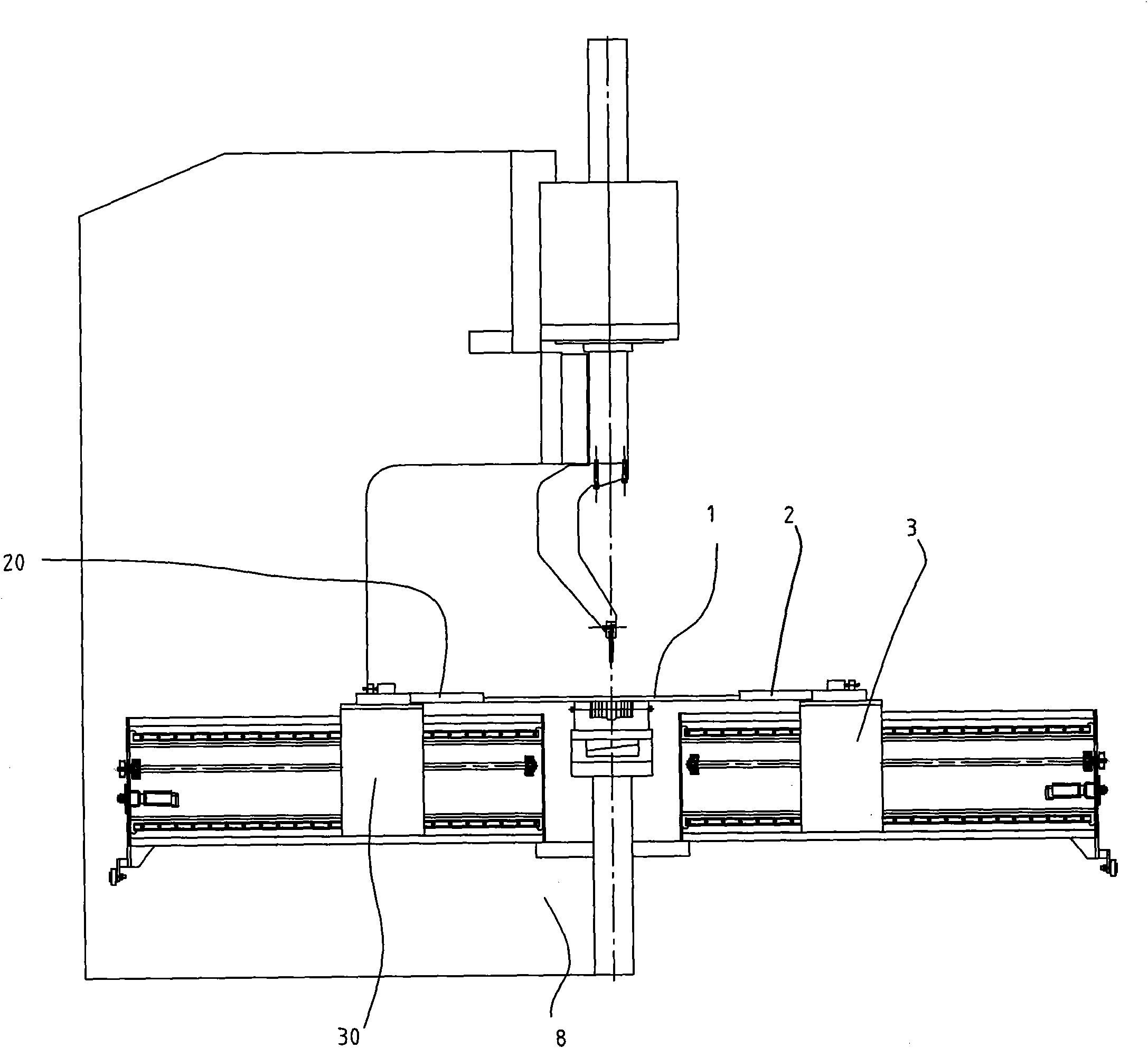
[0013] The present invention as figure 1 , 2 , 3, set at the front and / or rear of the bending machine 8 workbench, including a bracket 6, a moving frame 3, a screw rod 5 arranged on the bracket 6 for driving the moving frame 3 to move forward and backward, and a finger 2 and a pneumatic buffer compensation device 4; the finger 2 is arranged on the moving frame 3, and the working surface of the finger 2 faces the blade of the bending machine 8; the moving frame 3 passes through the pneumatic buffer compensation device 4 links to each other with described screw mandrel 5.

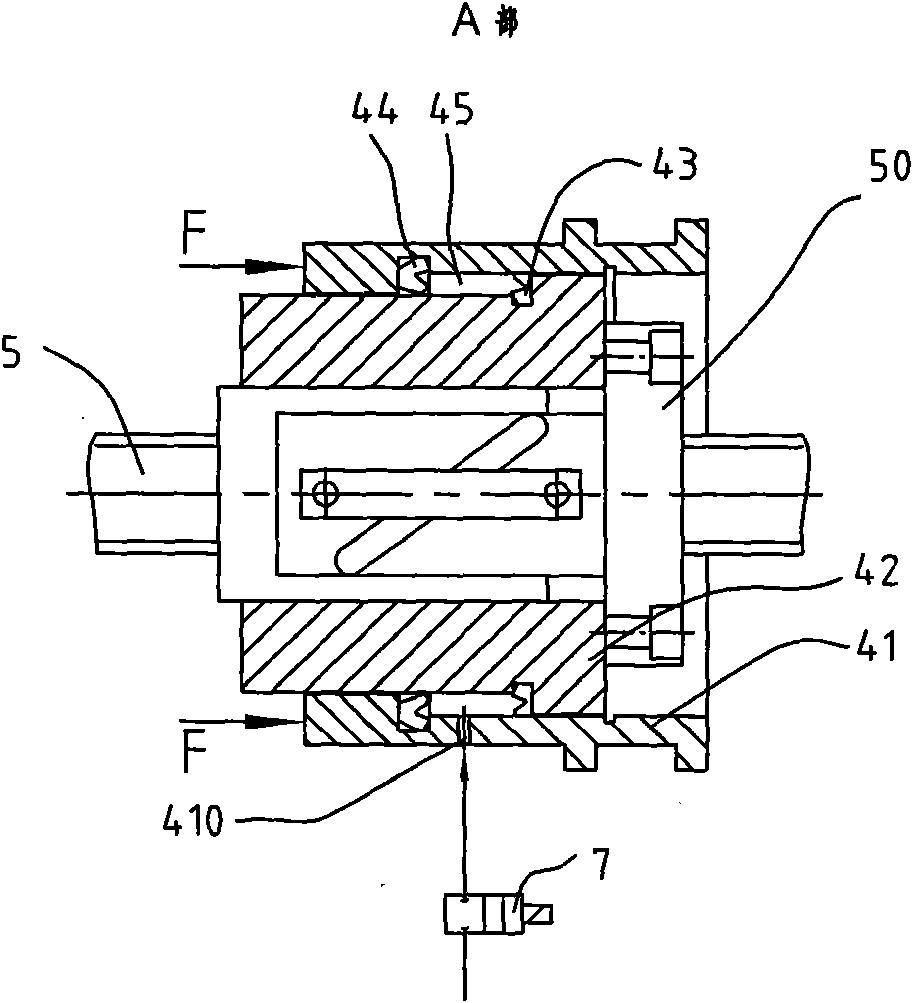
[0014] The pneumatic buffer compensation device 4 includes a screw nut 50 for screw connection with the screw rod 5 , a piston 42 sleeved outside the screw nut 50 and a cylinder sleeve 41 sleeved outside the piston 42 The cylinder liner 41 is fixedly connected to the moving frame 3; there is a pressure air cavity 45 between the cylinder liner 41 and the piston 42, which can make the moving frame 3 perform a...


PUM


Abstract

The invention relates to a plate positioning device on a bending machine, which can avoid the influence of inertia generated during plate feed-in on the position of a stop pin to improve positioning accuracy. The plate positioning device is arranged on the front and/or rear part of a workbench of the bending machine, and comprises a support, a movable frame, a screw rod which is arranged on the support and is used for driving the movable frame to move back and forth, the stop pin and a pneumatic buffer compensating device, wherein the stop pin is arranged on the movable frame, and a work surface of the stop pin faces a blade of the bending machine; and the movable frame is connected with the screw rod by the pneumatic buffer compensating device. After the stop pin on stopping materials is subjected to the impact force of plates, the impact force can be transferred to a ball screw rod, so that the ball screw rod can be damaged to finally cause the invalidation of the positioning accuracy finally. Therefore, the impact force is prevented from being acted on the ball screw rod directly by utilizing the pneumatic buffer compensating device, so that when the screw rod is subjected to the impact force, the accuracy of the screw rod is not influenced. The plate positioning device has the advantages of high accuracy, high impact resistance, long service life and the like.

Description

technical field [0001] The invention relates to a sheet material positioning device of a bending machine, in particular to a sheet material positioning device capable of "unloading" the impact force of feeding on an automatic production line. Background technique [0002] During the processing of the bending machine, the positioning accuracy of the sheet is very important, and there are mostly tolerance requirements between the positioning edge and the bending deformation. In the past, when feeding manually, the operator would carefully place the sheet at the specified position so that no large impact force would be generated between the positioning edge and the positioning block. Now the automatic line is widely used. When the automatic feeding device sends the sheet to the processing position, it often has a large inertia. If the positioning block is rigidly connected to the workbench, it will rebound. For precise positioning, movable stoppers are generally arranged in fr...

Claims


Application Information

Patent Timeline
IPC IPC(8): B21D5/00B21D43/00
Inventor 曹光荣王洪奎谈传明王成国毛志强冷志斌
Owner JIANGSU YAWEI MACHINE TOOL
Why Eureka
Try Eureka