Cable retainer

A technology of retainer and retainer, applied in the direction of cable, insulated cable, cable installation, etc.

Inactive Publication Date: 2011-08-03
FUJITSU FRONTECH LTD
View PDF7 Cites 6 Cited by
  • Summary
  • Abstract
  • Description
  • Claims
  • Application Information

AI Technical Summary

Problems solved by technology

[0008] Therefore, since the volume of cables that can be accommodated in the connection member of the conventional cable holder is fixed, it is impossible to flexibly cope with the increase in wiring capacity

Method used


Image

  • Cable retainer
  • Cable retainer
  • Cable retainer

Examples


Embodiment Construction

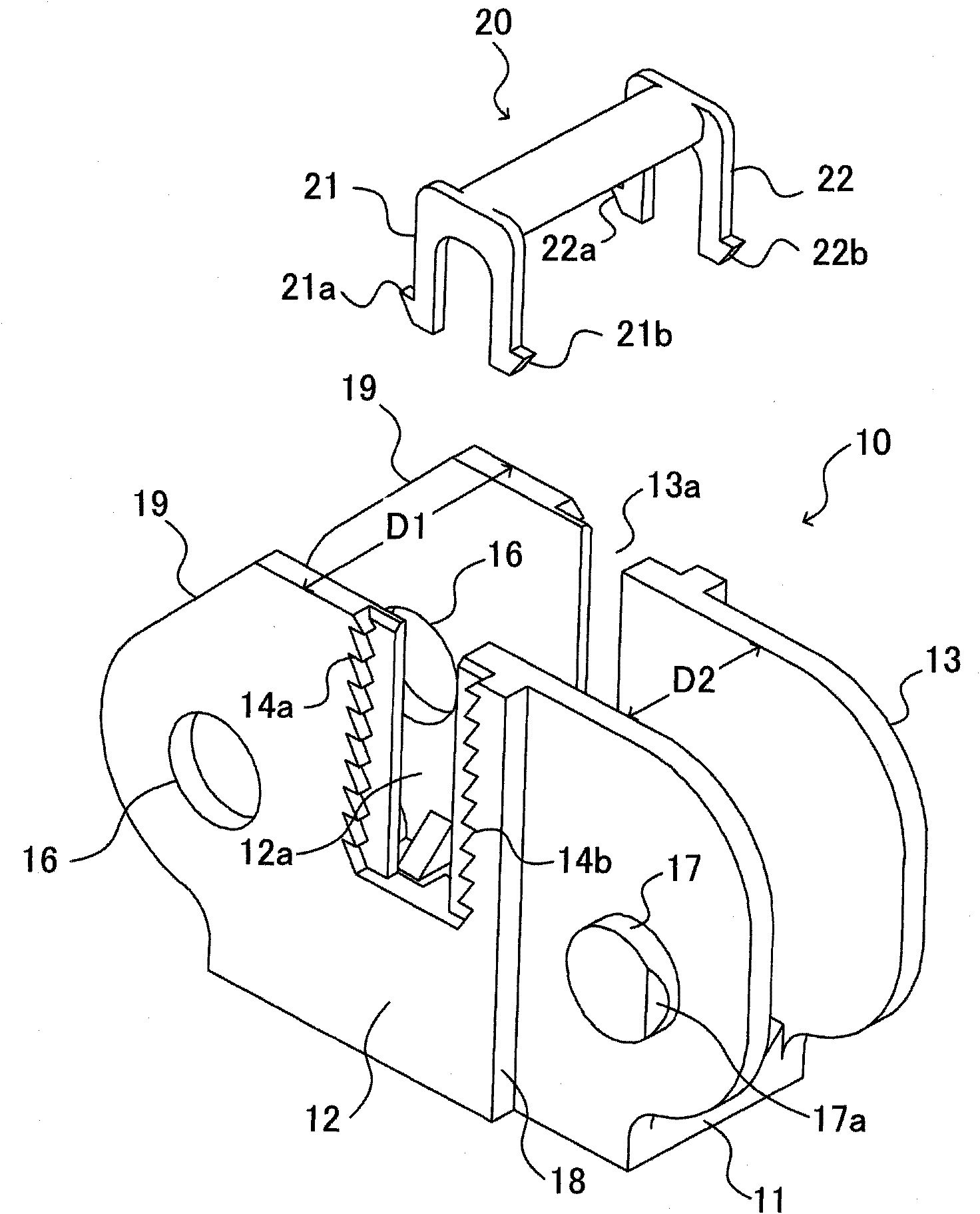
[0015] Embodiments of the present invention will now be described with reference to the drawings, wherein like reference numerals refer to like elements throughout. figure 1 is a perspective view of a cable retainer body and a beam member according to an embodiment of the present invention.

[0016] figure 1 A single connection member is shown, formed of the cable holder body 10 and the beam member 20 as its constituent elements. The cable holder main body 10 includes a bottom plate 11 having a predetermined width D1, and lateral side plates 12 and 13 vertically rising from the bottom plate 11 to a predetermined height. The cable holder main body 10 is formed of an elastic material and has a U-shaped cross-sectional inner space defined by side plates 12 and 13 with a space width D2 so that at least one cable (not shown) can be inserted. That is, although depending on the cable diameter, when one or more cables are inserted into the cable holder main body 10 from the opening ...


PUM


Abstract

The present invention provides a cable retainer which has a plurality of link members coupled to each other in a bendable manner for retaining a plurality of cables therein. When vertically moving a beam member along slits formed in opposite side plates of a cable retainer body, the beam member is positioned and fixed by causing engagement lugs of leg portions of the beam member to be engaged with serrated surfaces of side plates. Therefore, it is possible to adjust the fixing position of the beam member according to the wiring volume of cables to be retained, whereby it is possible to make the wiring capacity of link members variable.

Description

technical field [0001] Embodiments discussed herein relate to a cable holder having a plurality of connecting members each formed into the same shape and coupled to each other for holding at least one cable therein in a bendable manner. Background technique [0002] In equipment such as industrial robots having a movable part that moves relative to the main unit of the machine, it is often the case that wiring must be installed between the main unit of the machine and the movable part. In this case, if the cables connected between the main unit of the machine and the movable parts are exposed, they are liable to be damaged, for example, by contact with external members, thus causing fear of disconnection of the cables or the like . Furthermore, in the case where a main unit of a communication device or an electronic device is electrically connected by a cable to a movable unit that can be pulled out from the main unit, the cable must be held so as to prevent the cable from ...

Claims


Application Information

Patent Timeline
Patent Type & Authority Applications(China)
IPC IPC(8): H02G11/00
CPCF16G13/16H02G3/32H01B7/40
Inventor 江上博之
Owner FUJITSU FRONTECH LTD
Why Eureka
Try Eureka