Installing method for main pipeline of coolant system of nuclear power station

A technology of coolant system and installation method, which is applied in nuclear power generation, nuclear engineering, nuclear reactor monitoring and other directions, can solve the problems of large diameter and wall thickness of main pipeline, high welding quality requirements, and large construction period risks, so as to improve work efficiency and save money. material, effect of reducing the number of welds

Active Publication Date: 2011-08-31
CHINA NUCLEAR IND FIFTH CONSTR CO LTD
View PDF6 Cites 45 Cited by
  • Summary
  • Abstract
  • Description
  • Claims
  • Application Information

AI Technical Summary

Problems solved by technology

The diameter and wall thickness of the main pipeline of the nuclear power plant are relatively large, which requires high welding quality; all the equipment connected to the main pipeline is nuclear safety first-level equipment, with complex structure, long manufacturing cycle and high risk of construction period

Method used


Image

  • Installing method for main pipeline of coolant system of nuclear power station
  • Installing method for main pipeline of coolant system of nuclear power station
  • Installing method for main pipeline of coolant system of nuclear power station

Examples


Embodiment 1

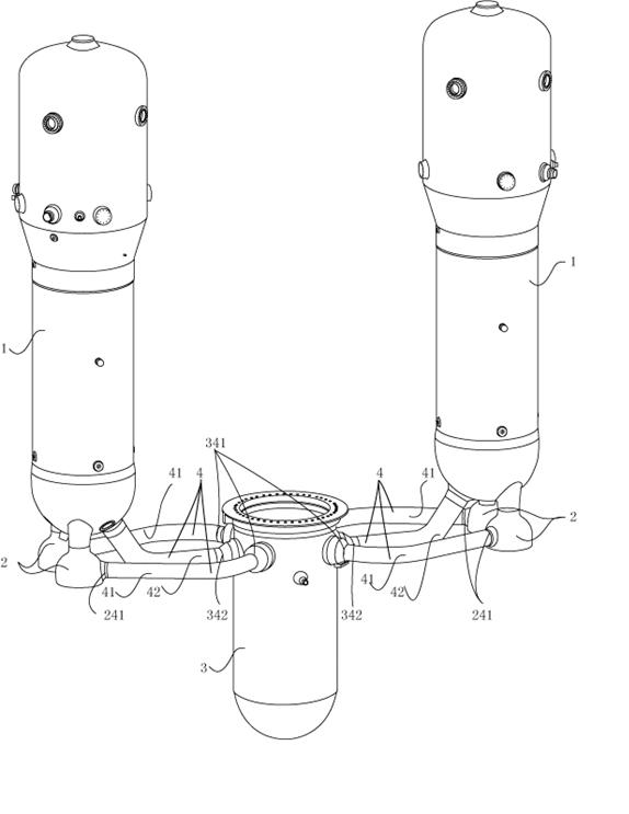
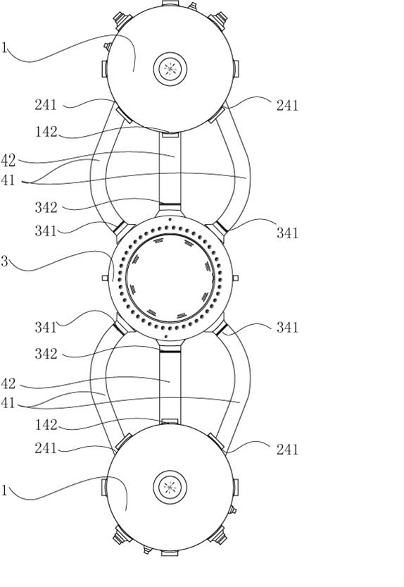
[0045] This embodiment first starts from the end of the pressure vessel 3 of the main pipeline 4 and installs towards the end of the steam generator 1, which is applicable to the situation that the steam generator 1 has not arrived and the pressure vessel 3 has arrived; the installation method is described in detail as follows:

[0046] 1) Install prerequisite check.

[0047] 2) The pressure vessel 3 is installed in place. If the steam generator 1 has not arrived, the steam generator and main pump will not be installed temporarily.

[0048] 3) Use laser tracking to measure pressure vessel 3, obtain nozzle data, and perform 3D modeling according to the data; if steam generator 1 has not arrived, you can directly refer to the measurement data provided by the supplier, or go to the supplier for inspection The data of steam generator 1 and main pump 2 are measured by laser tracking and 3D modeling is carried out.

[0049] 4) Laser tracking and measuring the cold and hot sections ...

Embodiment 2

[0067] This embodiment first starts from the steam generator 1 end of the main pipeline 4, and installs to the pressure vessel 3 end. It is suitable for the steam generator 1, the main pump 2 has arrived, and the pressure vessel 3 has not arrived. The installation method is described in detail as follows :

[0068] 1) Install prerequisite check.

[0069] 2) The steam generator 1 and the main pump 2 are installed in place. If the pressure vessel 3 has not arrived, it will not be installed temporarily.

[0070] 3) Use laser tracking to measure the nozzles of steam generator 1 and main pump 2. If the pressure vessel 3 has not arrived, you can directly refer to the data provided by the supplier; or go to the supplier for laser measurement of the nozzle data of pressure vessel 3 Track measurements and perform 3D modeling according to the data.

[0071] 4) Laser tracking and measuring the cold and hot sections of the main pipeline to obtain data, and perform 3D modeling and data f...

Embodiment 3

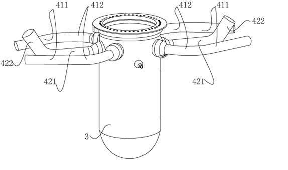
[0089] In this embodiment, the curved portion of the main pipe 4 is butt-welded first, and then the straight section is butt-welded, which is applicable when the steam generator 1 and the pressure vessel 3 have both arrived. Or measure the 3D data of the safety end nozzle and groove at the manufacturer, which is convenient to save on-site construction period. Its installation method is detailed as follows:

[0090] 1) Prerequisite checks.

[0091] 2) Laser tracking and measuring the nozzles of steam generator 1, main pump 2, and pressure vessel 3 to obtain data, and perform 3D modeling according to the data.

[0092] 3) Laser tracking and measuring the 4 cold and hot sections of the main pipeline to obtain data, and perform 3D modeling according to the data, and perform laser measurement on the groove characteristics of the main pipeline to be processed to obtain data confirmation, and perform 3D modeling and groove group pair fit. .

[0093] 4) Use the on-site CNC trackin...


PUM


Abstract

The invention relates to an installing method for a main pipeline of a coolant system of a nuclear power station, which is characterized in that the main pipeline of the coolant system of a reactor of the pressurized water reactor nuclear power station comprises a cool section (41) and a hot section (42), and a steam generator is directly connected with a main pump. According to the invention, the problem that the main pipeline is installed and welded by only a pressure container or steam generator in place by adopting the installing method of the main pipeline without a transition section issolved, and technical limit that the main pipeline is installed after the pressure container is in place and the steam generator or main pump is in place in the traditional main pipeline constructiontechnology is eliminated. A main pipeline groove is processed by adopting a site numerical control machining technology, the main pipeline and equipment connected with the main pipeline are subjectedto measurement, modeling and process monitoring by adopting a laser tracking measuring and 3D modeling technology, the main pipeline is regulated to meet the assembly welding requirement and is installed by using a narrow TIG (argon tungsten-arc welding) automatic welding technology, thus a feasible method is provided for shortening the construction period of the nuclear power station.

Description

technical field [0001] The invention relates to a method for installing a reactor coolant system main pipeline of a pressurized water reactor nuclear power plant. Background technique [0002] The reactor coolant system pipeline (hereinafter referred to as the main pipeline) of the nuclear power plant is connected to the reactor pressure vessel (hereinafter referred to as the pressure vessel), the steam generator and the reactor coolant pump (hereinafter referred to as the main pump) (the above four items are collectively referred to as the main equipment of the nuclear island) The closed circulation loop of the pressurized water reactor nuclear power plant is the most critical nuclear safety first-level equipment, and the medium in the tube is boron-containing water with radioactivity. The main pipeline of each loop of the coolant system includes: a hot section connecting the pressure vessel and the steam generator, and two cold sections connecting the pressure vessel and t...

Claims


Application Information

Patent Timeline
Patent Type & Authority Applications(China)
IPC IPC(8): G21C19/00G21C17/00
CPCG21C17/00G21C21/00Y02E30/40G21C13/032G21C13/02Y10T29/49826Y02E30/30
Inventor 梁选翠刘卫华李建董培科谭敦权李永庆居海兵王荣敏魏宏兵徐斌苟锐李云扬李炜郭强覃明保王晓
Owner CHINA NUCLEAR IND FIFTH CONSTR CO LTD
Why Eureka
Try Eureka