Measuring method and device for coefficients of thermal expansion

A technology of thermal expansion coefficient and measurement method, applied in the direction of material thermal expansion coefficient, etc., can solve the problems of small deviation error of optical path, high equipment cost, strict preparation requirements, etc., and achieve the effect of eliminating system error, high test accuracy and high sensitivity

Active Publication Date: 2011-09-07
WUHAN SCHWAB INSTR TECH
View PDF4 Cites 21 Cited by
  • Summary
  • Abstract
  • Description
  • Claims
  • Application Information

AI Technical Summary

Problems solved by technology

Among them, the ejector rod expansion method is a non-absolute measurement method, which needs further calibration work, and this method belongs to contact measurement, the mechanical stress between the rod and the sample will affect the accuracy of the test results, so its test accuracy is relatively Low; the two beams of light that interfere in the Michelson interferometry come from the reflection of the sample and the standard, and the inevitable thermal expansion of the standard and the sample stage will affect the accuracy of the test, and the method of reading the number of interference fringes will Introducing random errors, the test results are not intuitive, and only the average thermal expansion coefficient of a certain temperature zone can be measured
The measurement method of the thermal expansion coefficient shown in the Chinese invention patent "A Two-beam Laser Interferometry of Thermal Expansion Coefficient of Material" (publication number CN101140249B, publication date 2010.09.01) does not include the measurement method of the thermal expansion coefficient of light-transmitting materials, and it uses The most important thing is the two beams of incident light, it is difficult to completely guarantee the identity of the two beams of laser light, the incident angle of the two beams of light and the slight deviation of the optical path during the transmission process will produce large errors, so this method is very important for the selection of the light source and the adjustment of the optical path. The adjustment and sample preparation requirements are more stringent, and the equipment cost is higher

Method used


Image

  • Measuring method and device for coefficients of thermal expansion
  • Measuring method and device for coefficients of thermal expansion
  • Measuring method and device for coefficients of thermal expansion

Examples


Embodiment Construction

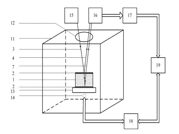
[0021] The present invention will be further described below in conjunction with drawings and embodiments.

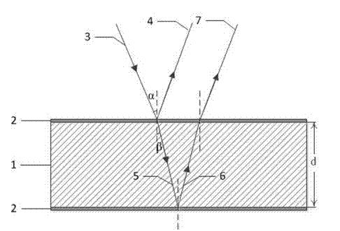
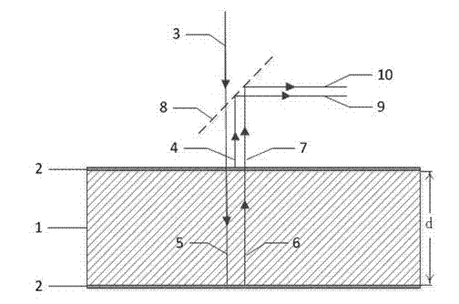
[0022] figure 1 It is a schematic diagram of the measurement method of the present invention. The upper and lower surfaces of the light-transmitting material 1 to be tested are parallel to each other, and the distance d between the upper and lower surfaces at room temperature can be accurately measured with a vernier caliper. Generally, the distance d should be greater than 1 mm and less than 1000 mm.

[0023] Then, the upper and lower parallel surfaces of the light-transmitting material 1 to be tested are respectively coated with a thin film 2 that is partly light-transmitting and partially reflective. The main function of the film 2 is to form two reflective interfaces on the upper and lower surfaces of the light-transmitting material 1 to be tested. , its reflectivity should be greater than 10% to ensure sufficient reflected light intensity; in order to allow the in...


PUM

PropertyMeasurementUnit
thicknessaaaaaaaaaa
thicknessaaaaaaaaaa
transmittivityaaaaaaaaaa

Abstract

The invention discloses a measuring method and a measuring device for coefficients of thermal expansion. The measuring method comprises the following steps of: plating a layer of membrane which transmits light partially and reflects the light partially on upper and lower surfaces of a light transmission material to be measured respectively; heating the light transmission material; allowing a beamof monochromatic light to be incident to the light transmission material to be measured in the heating process, and reflecting the monochromatic light on the upper and lower surfaces of the light transmission material respectively, so that two beams of reflected light are interfered with each other; detecting the power of the interfered reflected light, finding a temperature value corresponding to the maximum value of the power of the reflected light, and determining the change period of the power of the reflected light in preset temperature intervals of the light transmission material; and calculating according to the change period to obtain the coefficients of thermal expansion of the light transmission material to be measured in the temperature intervals. By the measured method, the coefficients of thermal expansion of the light transmission material can be measured accurately, the test accuracy is relatively high, and system error caused by thermal expansion of sample frames and the like can be eliminated effectively; and due to the adoption of a single light source, a light path is simple, the cost is low, and the thermal expansion condition of each temperature interval can be reflected visually.

Description

technical field [0001] The invention belongs to the technical field of material thermal performance testing, and in particular relates to a method for measuring the thermal expansion coefficient of a light-transmitting material. Background technique [0002] The coefficient of thermal expansion is one of the important parameters to characterize the thermophysical properties of materials. For the material under the condition of temperature change, its thermal expansion coefficient will determine the ability of the material to resist thermal shock, the magnitude of thermal stress and the degree of thermal deformation. For example, all aerospace vehicles, launch vehicles, and gun bores will undergo different degrees of aerodynamic heating during operation and use. Materials with a small thermal expansion coefficient must be used to avoid coating peeling or even disintegration of the whole machine due to thermal deformation. and other serious consequences; in the process of hou...

Claims


Application Information

Patent Timeline
Patent Type & Authority Applications(China)
IPC IPC(8): G01N25/16
Inventor 缪向水童浩程晓敏
Owner WUHAN SCHWAB INSTR TECH
Why Eureka
Try Eureka