Two-dimensional photoelectric auto-collimation method and device for polarized light pyramid target common-path compensation

A photoelectric self-collimation and polarized light technology, applied in the direction of using optical devices, measuring devices, optics, etc., can solve the problems that restrict the improvement of the final angle measurement accuracy, the transmission paths of the measurement beam and the reference beam do not coincide, and the directionality of the incident light source is required. High and other problems, to achieve the effect of simple and convenient application and improved anti-interference ability

Inactive Publication Date: 2011-09-07
HARBIN INST OF TECH
View PDF4 Cites 58 Cited by
  • Summary
  • Abstract
  • Description
  • Claims
  • Application Information

AI Technical Summary

Problems solved by technology

[0019] (1) In the method of collimation using the spatial connection of diffraction or interference fringes produced by zone plate, phase plate, binary optical device or double slit, etc., the directionality of the incident light source is required to be high, and the incident light source cannot be suppressed The influence of angular drift, the angular drift of the incident light source directly leads to the drift of the collimation baseline, and the ability to suppress air disturbance in the transmission path is limited;
[0020] (2) In the method of dual optical path compensation, it is difficult to generate symmetrical double beams, and the transmission paths of the measurement beam and the reference beam in the dual optical paths do not coincide, so

Method used


Image

  • Two-dimensional photoelectric auto-collimation method and device for polarized light pyramid target common-path compensation
  • Two-dimensional photoelectric auto-collimation method and device for polarized light pyramid target common-path compensation
  • Two-dimensional photoelectric auto-collimation method and device for polarized light pyramid target common-path compensation

Examples


specific Embodiment approach 1

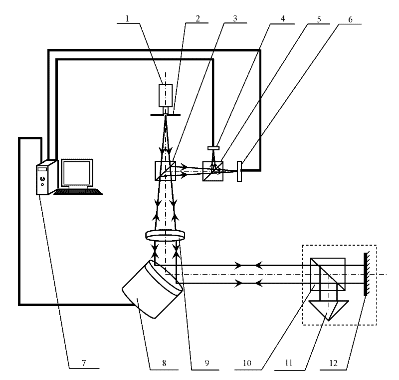
[0055] Specific implementation mode one: the following combination figure 1 To illustrate this embodiment, the two-dimensional photoelectric self-collimation method for the common optical path compensation of the polarization pyramid target described in this embodiment includes the following steps:

[0056] Step 1. A beam of polarized beam emitted by the laser light source passes through the reticle, beam splitter and collimating objective lens to form a collimated beam and emit it;

[0057] Step 2. After the collimated beam is reflected by the two-dimensional beam deflection device, it enters the first polarizing beam splitter, and the first polarizing beam splitter divides the incident beam into a transmitted beam and a reflected beam whose polarization states are perpendicular to each other;

[0058] The transmitted beam obtained in step 3 and step 2 is used as the measuring beam after being reflected by the measuring mirror, and the measuring beam obtains the two-dimension...

specific Embodiment approach 2

[0068] Specific implementation mode two: the following combination figure 1Describe this embodiment, the device for implementing the two-dimensional photoelectric self-collimation method for the common optical path compensation of the polarization pyramid target described in the first embodiment, which includes a two-dimensional photoelectric self-collimation light tube, and a drift amount based on the pyramid combination target monitoring separation device, two-dimensional beam deflection device 8, measuring mirror 12 and controller 7,

[0069] Two-dimensional photoelectric self-collimating light pipe: including laser light source 1, reticle 2, beam splitter 3, first photoelectric position sensor 6 and collimating objective lens 9;

[0070] The drift monitoring separation device based on the pyramid combination target: including the first polarization beam splitter 10, the pyramid reflection mirror 11, the second polarization beam splitter 5 and the second photoelectric posit...

specific Embodiment approach 3

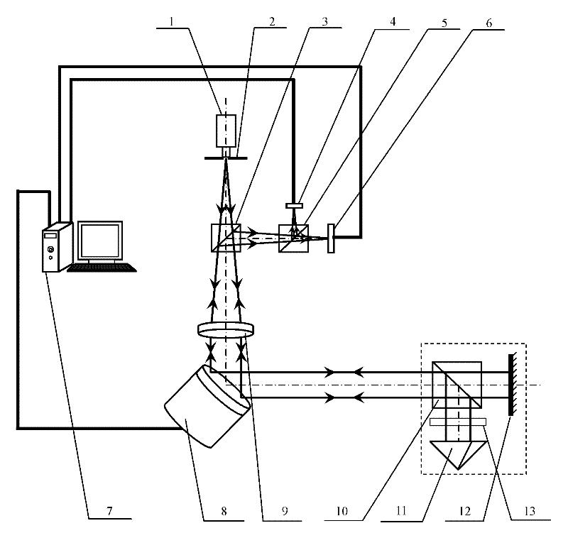
[0078] Specific implementation mode three: the following combination figure 2 Describe this embodiment, the difference between this embodiment and Embodiment 2 is: it also includes the first 1 / 4 wave plate 13, the first polarization beam splitter 10, the corner mirror 11, the measuring mirror 12 and the first The 1 / 4 wave plate 13 is cured and packaged into a pyramid combination target, and the first 1 / 4 wave plate 13 is arranged between the first polarization beam splitter 10 and the pyramid mirror 11 . Other components and connections are the same as those in Embodiment 2.


PUM


Abstract

The invention discloses a two-dimensional photoelectric auto-collimation method and device for polarized light pyramid target common-path compensation, belonging to the technical field of precision instrument manufacture and precision measurement. According to the invention, high-precision photoelectric autocollimation angle measurement is realized for solving the defects in the existing method and device. The method comprises: a common-path shift quantity monitoring separating device based on a pyramid combined target can be used for curing a polarizing light splitter, a pyramid reflector and a measurement reflector to form the pyramid combined target, and separating a reference light beam which has a feature identical to that of a measurement light beam and is in common-path transmission with the measurement light beam while obtaining a two-dimensional angle variation by using the linear polarization feature of the laser; a controller is used for controlling a two-dimensional light beam deflection device in real time according to the shift quantity reflected by the reference light beam so as to inhibit the shift quantity coupled in the measurement light beam, thus the precision measurement on the two-dimensional angle variation is realized. The device for realizing the method comprises a two-dimensional photoelectric auto-collimation tube, the common-path shift quantity monitoring separating device based on the pyramid combined target, the controller and the two-dimensional light beam deflection device.

Description

technical field [0001] The invention relates to a two-dimensional photoelectric self-collimation method and device for common optical path compensation of polarized light pyramid targets, belonging to the technical fields of precision instrument manufacturing and precision testing and measurement. Background technique [0002] With the continuous development of precision manufacturing processing technology and measurement technology, higher and higher requirements are put forward for the measurement accuracy of two-dimensional small angle. The photoelectric self-collimation angle measurement method is widely used in small angle measurement, high-precision angle calibration, flatness measurement of flat plate, angular shake measurement of shaft system, straightness measurement of guide rail, position uncertainty of turntable and other measurement fields. It is a necessary routine measuring instrument for manufacturing, shipbuilding, aerospace, metrology testing, scientific re...

Claims


Application Information

Patent Timeline
IPC IPC(8): G02B27/30G02B27/28G01B11/26
Inventor 谭久彬朱凡崔继文
Owner HARBIN INST OF TECH
Why Eureka
Try Eureka