Polarized light combined target common-path compensated two-dimensional photoelectric auto-collimation method and device

A photoelectric self-collimation and polarized light technology, applied in the direction of optical devices, measuring devices, optics, etc., can solve the problem of difficult application of self-collimation angle measurement, restrictions on the improvement of the final angle measurement accuracy, and high requirements for the directionality of incident light sources, etc. question

Active Publication Date: 2012-07-25
哈尔滨超精密装备工程技术中心有限公司
View PDF1 Cites 1 Cited by
  • Summary
  • Abstract
  • Description
  • Claims
  • Application Information

AI Technical Summary

Problems solved by technology

[0019] (1) In the method of collimation using the spatial connection of diffraction or interference fringes produced by zone plate, phase plate, binary optical device or double slit, etc., the directionality of the incident light source is required to be high, and the incident light source cannot be suppressed The influence of angular drift, the angular drift of the incident light source directly leads to the drift of the collimation baseline, and the ability to suppress air disturbance in the transmission path is limited;
[0020] (2) In the method of dual optical path compensation, it is difficult to generate symmetrical double beams, and the transmission paths of the measurement beam and the reference beam in the dual optical paths do not coincide, so that the characteristics of the beams in the two optical paths are not completely consistent, and the reference beam cannot fully reflect the measurement. The drift of the beam, the compensation effect is not good;
[0021] (3) In the way of closed-loop feedback control, most of the closed-loop feedback is used to improve the stability of the laser light in a specific direction, which is difficult to apply to the measurement of the self-collimation angle, and the reference beam and the measurement beam cannot be transmitted in the same optical path, so the reference beam Not completely consistent with the characteristics of the measuring beam, which makes the compensation effect poor and restricts the improvement of the final angle measurement accuracy

Method used


Image

  • Polarized light combined target common-path compensated two-dimensional photoelectric auto-collimation method and device
  • Polarized light combined target common-path compensated two-dimensional photoelectric auto-collimation method and device
  • Polarized light combined target common-path compensated two-dimensional photoelectric auto-collimation method and device

Examples


specific Embodiment approach 1

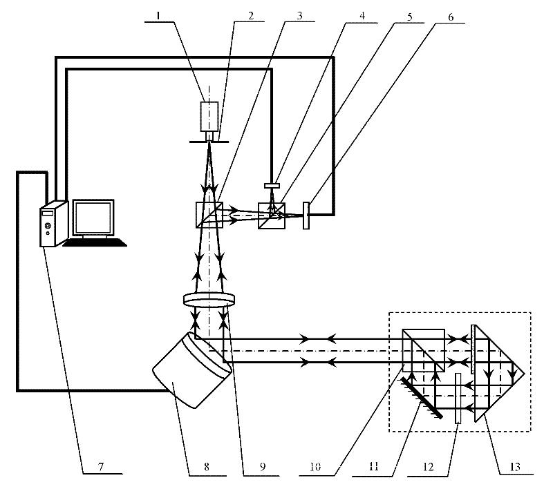
[0051] Specific implementation mode one: the following combination figure 1 To illustrate this embodiment, the two-dimensional photoelectric self-collimation method for the common optical path compensation of the polarized light combination target described in this embodiment includes the following steps:

[0052] Step 1. A linearly polarized beam emitted by the laser light source passes through the reticle, the beam splitter and the collimating objective lens to form a collimated beam and emit it;

[0053] Step 2. After the collimated beam is reflected by the two-dimensional beam deflection device, it enters the first polarizing beam splitter, and the first polarizing beam splitter transmits all the incident beam, and the transmitted beam enters the spectroscopic target detector, so The above-mentioned spectroscopic target detector separates the light beam into a reflected light beam and a transmitted light beam;

[0054] The reflected light beam obtained in step 3 and step ...

specific Embodiment approach 2

[0064] Specific implementation mode two: the following combination figure 1 and figure 2Describe this embodiment, the device for implementing the two-dimensional photoelectric self-collimation method for compensation of the common optical path of the polarized light combination target described in the first embodiment, which includes a two-dimensional photoelectric self-collimation light tube, and drift monitoring based on the detector combination target Separation device, two-dimensional beam deflection device 8, spectroscopic target detector 13 and controller 7,

[0065] Two-dimensional photoelectric self-collimating light pipe: including laser light source 1, reticle 2, beam splitter 3, first photoelectric position sensor 6 and collimating objective lens 9;

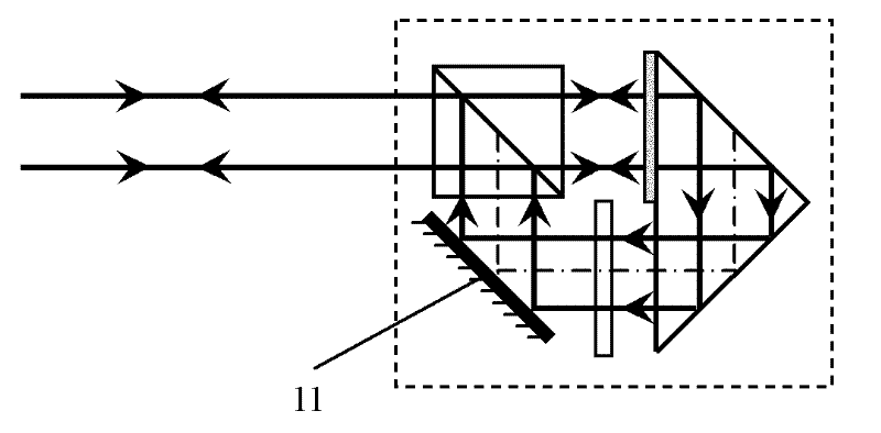
[0066] Monitoring and separation device based on the drift of the combined detector target: including a first polarization beam splitter 10, a mirror 11, a 1 / 2 wave plate 12, a spectroscopic target detector 13, a sec...

specific Embodiment approach 3

[0073] Specific implementation mode three: the following combination image 3 This embodiment will be described. The difference between this embodiment and the second embodiment is that the reflecting mirror 11 is a plane reflecting mirror. Other components and connections are the same as those in Embodiment 2.


PUM


Abstract

The invention discloses a polarized light combined target common-path compensated two-dimensional photoelectric auto-collimation method and device, and the method and device provided by the invention belong to the technical field of precision instrument manufacture and precision measurement. According to the invention, the defects in the existing method and device are solved, and high-precision photoelectric autocollimation angle measurement is realized for solving. The method comprises: a common-path shift quantity monitoring separating device based on a detector combined target can be used for combining a polarizing light splitter, a light-split target detector, 1 / 2 wave plate and a reflector at 45 degrees to form the detector combined target, and can be used for separating a reference light beam in common-path transmission with a measurement light beam while obtaining the measurement light beam in two-dimensional angle variation by using a linear polarization feature of the laser; a controller is used for controlling a two-dimensional light beam deflection device in real time according to the shift quantity reflected by the reference light beam to inhibit the shift quantity coupled in the measurement light beam, the precision measurement on the two-dimensional angle variation is realized. The device for realizing the method comprises a two-dimensional photoelectric auto-collimation tube, the common-path shift quantity monitoring separating device based on the detector combined target, the controller and the two-dimensional light beam deflection device.

Description

technical field [0001] The invention relates to a two-dimensional photoelectric self-collimation method and device for common optical path compensation of combined polarized light targets, belonging to the technical fields of precision instrument manufacturing and precision testing and measurement. Background technique [0002] With the continuous development of precision manufacturing processing technology and measurement technology, higher and higher requirements are put forward for the measurement accuracy of two-dimensional small angle. The photoelectric self-collimation angle measurement method is widely used in small angle measurement, high-precision angle calibration, flatness measurement of flat plate, angular shake measurement of shaft system, straightness measurement of guide rail, position uncertainty of turntable and other measurement fields. It is a necessary routine measuring instrument for manufacturing, shipbuilding, aerospace, metrology testing, scientific r...

Claims


Application Information

Patent Timeline
Patent Type & Authority Patents(China)
IPC IPC(8): G02B27/30G02B27/28G01B11/26
Inventor 谭久彬朱凡崔继文
Owner 哈尔滨超精密装备工程技术中心有限公司
Why Eureka
Try Eureka