Fluid container unit

A fluid container and container technology, which is applied in the direction of containers, containers with multiple items, medical science, etc., can solve problems such as obstacles and disadvantages of compact equipment for using liquid medicine, and achieve improved workability, simple and rapid installation operations Effect

Active Publication Date: 2014-04-16
SARAYA CO LTD +1
View PDF5 Cites 2 Cited by
  • Summary
  • Abstract
  • Description
  • Claims
  • Application Information

AI Technical Summary

Problems solved by technology

Therefore, the injection part of the liquid medicine tank of the liquid medicine use equipment must also have two filling ports, which is an obstacle to the compactness of the liquid medicine use equipment.
In addition, when the filling port of the unit is installed on the injection part of the liquid medicine tank of the liquid medicine using equipment, the receiving ports of the injection part must be accurately connected to the two filling ports, which is also disadvantageous in terms of improving the installation workability.

Method used


Image

  • Fluid container unit
  • Fluid container unit
  • Fluid container unit

Examples


Embodiment Construction

[0077] Hereinafter, embodiments of the present invention will be described with reference to the drawings.

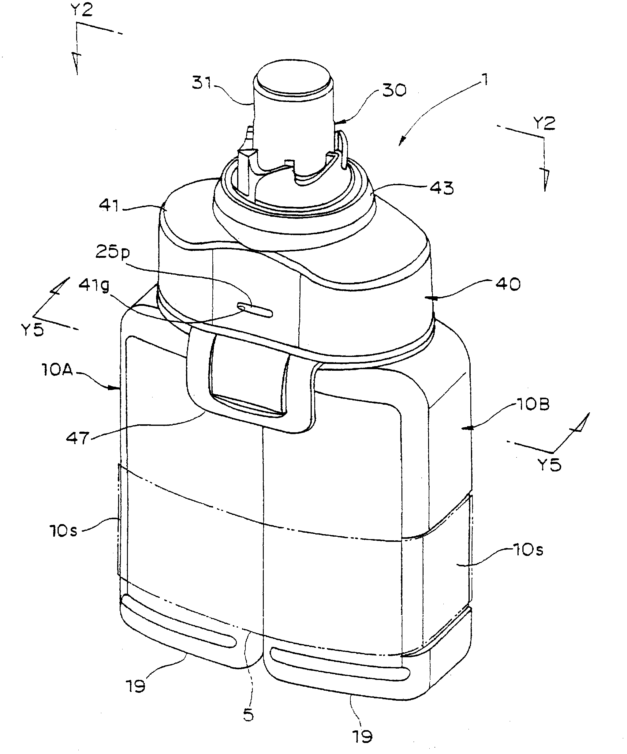
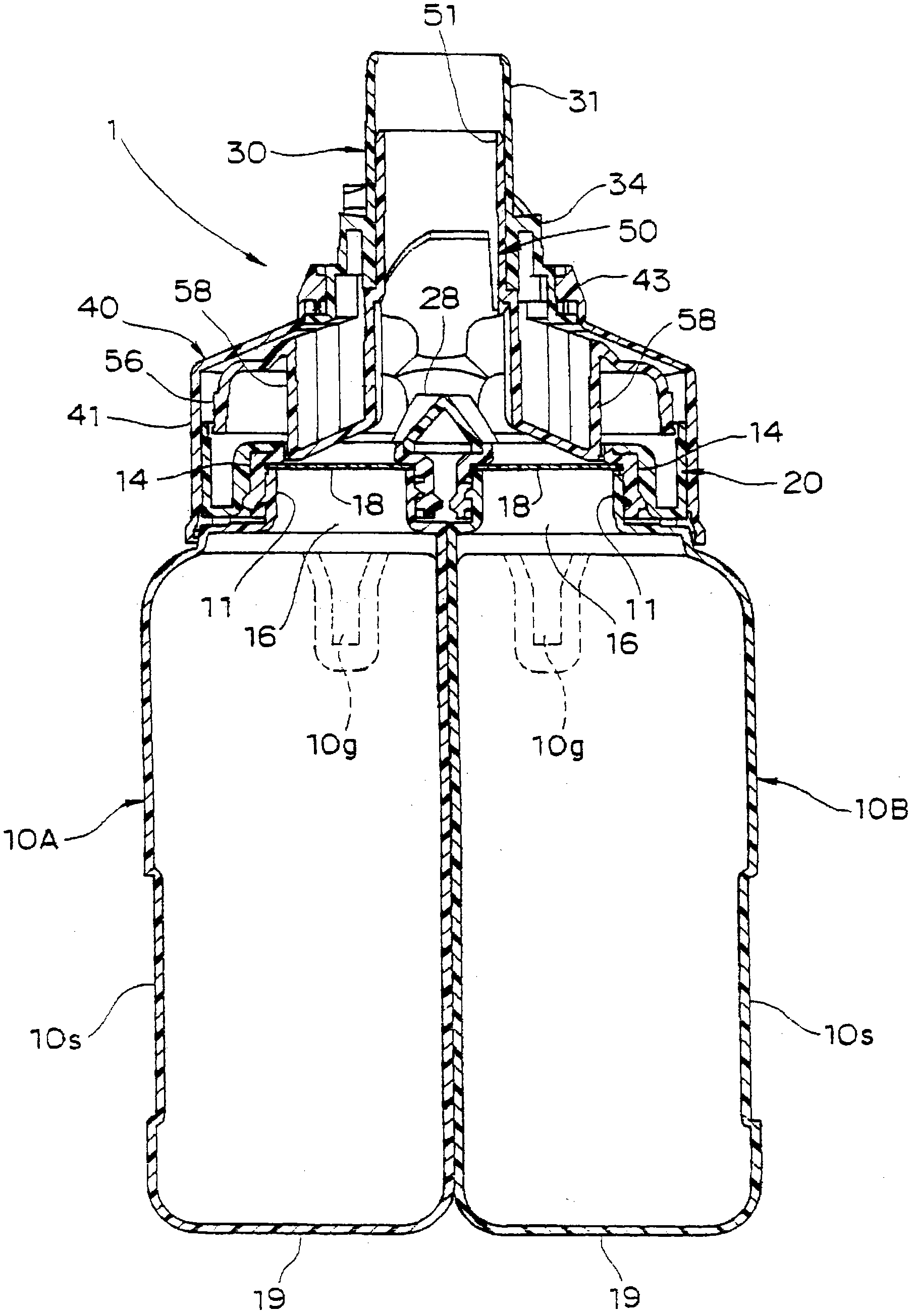
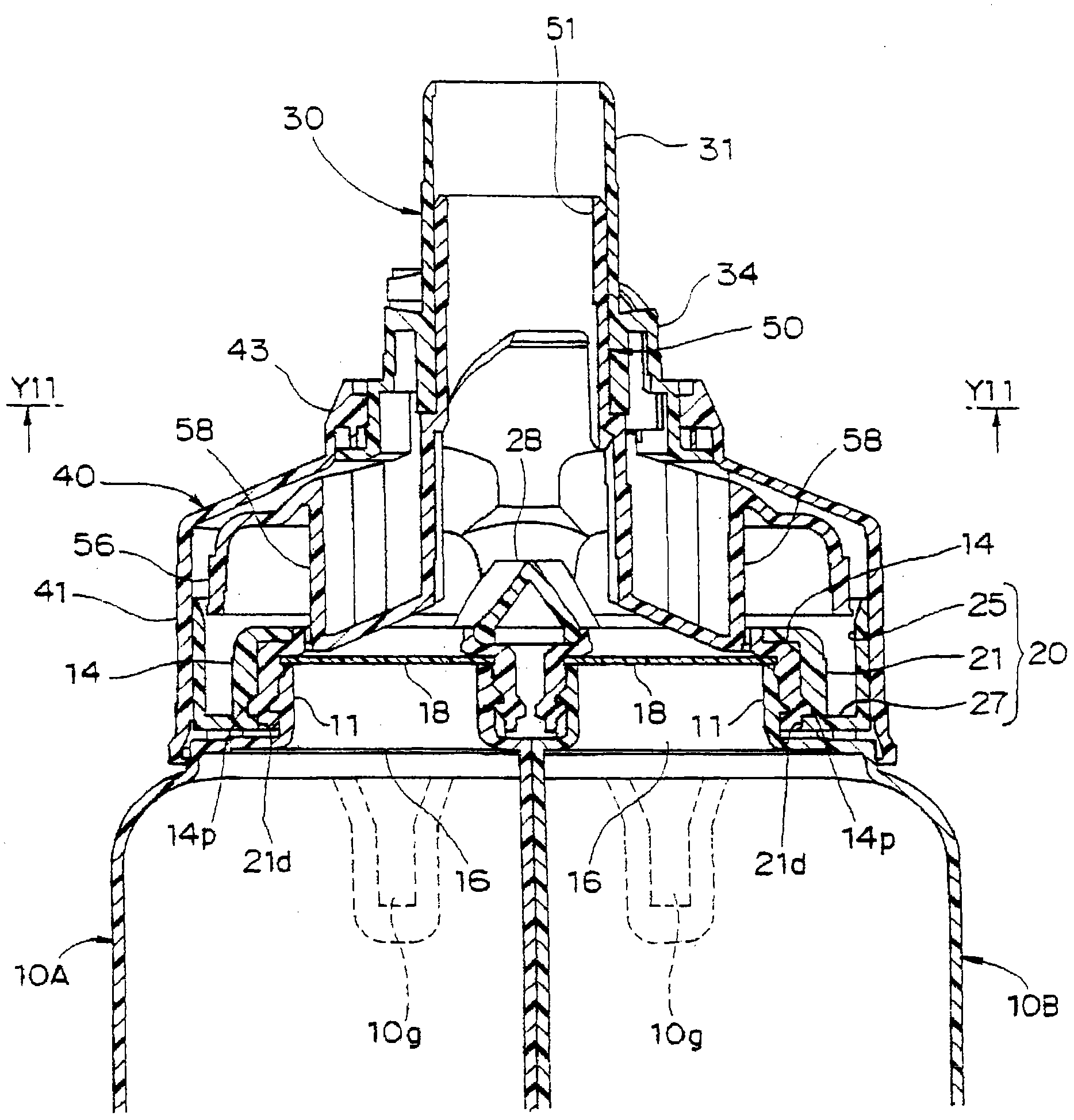
[0078] figure 1 is an overall perspective view showing the overall structure of the fluid container unit according to the present embodiment in a non-use state, figure 2 is along figure 1 The overall longitudinal sectional view of the fluid container unit of the Y2-Y2 line, image 3 is enlarged figure 2 The enlarged longitudinal section view of the main part of the main part of the fluid container unit, Figure 4 is a diagram showing the state of use of the fluid container unit, and is the same as image 3 Corresponding enlarged longitudinal sectional views of main parts. in addition, Figure 5 is to mean along figure 1 A perspective view of the cross-section of the fluid container unit of the Y5-Y5 line.

[0079] The fluid container unit 1 according to this embodiment is usually placed with the bottom surface 19 of each container 10A, 10B facing downward and ...


PUM


Abstract

The fluid container unit comprising: a container coupling for coupling a supply / discharge port of a first container with a supply / discharge port of a second container; a single nozzle member having a nozzle tube; a connection cap having one end for holding a base portion of the nozzle member and an other end for covering one side of the container coupling by fitting around an outer periphery thereof; an intermediate adaptor having a pair of pusher elements facing to the first and the second supply / discharge port respectively, and being held movably in a direction along a longitudinal axis of the nozzle tube in the connection cap, and a supply / discharge port opening mechanism for moving the intermediate adaptor toward the container coupling and opening the supply / discharge ports by the pusher elements. Thereby, in configuring a fluid container unit by integrally-assembling two containers for respectively accumulating different kinds of fluids in a parallel arrangement, the workability in fixing the fluid container unit to an injection site of a fluid usage equipment is improved, and the injection site can be configured to be more compact.

Description

technical field [0001] The present invention relates to a fluid container unit formed by assembling two containers storing fluids of different types into one body. Background technique [0002] At present, for example, in the case of cleaning or disinfecting relatively small medical appliances, etc., generally most of the methods used are: placing the object appliances that have undergone preliminary cleaning and other pre-treatments in a container of a certain volume (cleaning and disinfecting tank) ), and in this cleaning and disinfecting tank, a prescribed chemical solution (cleaning solution or disinfecting solution) is applied to the surface of the target utensil by spraying shower or dipping, etc., to perform cleaning or disinfection treatment. For example, Patent Document 1 discloses an endoscope cleaning and disinfection device for cleaning and disinfecting an endoscope using the method described above. [0003] As a chemical solution used in such a disinfection tre...

Claims


Application Information

Patent Timeline
Patent Type & Authority Patents(China)
IPC IPC(8): A61B1/12B65D81/32
CPCB65D81/3288A61B1/123B65D2251/0093B65D2251/0025
Inventor 西尾优小谷康二郎井上亮岩浪敬良佐藤慈之
Owner SARAYA CO LTD
Why Eureka
Try Eureka