Supercharge Your Innovation With Domain-Expert AI Agents!

System of first and second sections of a power module of a wind energy installation

A technology for power modules and wind energy equipment, applied in the field of systems consisting of the first and second sections of the power module of wind energy equipment, capable of solving problems such as connection troubles

Inactive Publication Date: 2017-04-05
SIEMENS AG
View PDF7 Cites 0 Cited by
  • Summary
  • Abstract
  • Description
  • Claims
  • Application Information

AI Technical Summary

Problems solved by technology

However, the connection of the flexible connecting rail to the preassembled conductor rail sections is complex, since the individual phase conductors of the conductor rail have to be connected individually to the associated phase conductors of the flexible connecting rail.

Method used


Image

  • System of first and second sections of a power module of a wind energy installation
  • System of first and second sections of a power module of a wind energy installation
  • System of first and second sections of a power module of a wind energy installation

Examples


Embodiment Construction

[0028] exist figure 1 The wind energy installation 1 shown schematically in the center comprises a tower 2 with a foundation 3 , a nacelle 4 mounted rotatably at the top of the tower, and a power module 5 arranged at the base of the tower.

[0029] Arranged within the nacelle 4 is a rotor with rotor blades 6 mounted rotatably about a horizontal axis, as well as a generator 7 . The rotor is set into rotation by the wind force acting on the rotor blades 6 and drives a generator 7 for generating electrical energy.

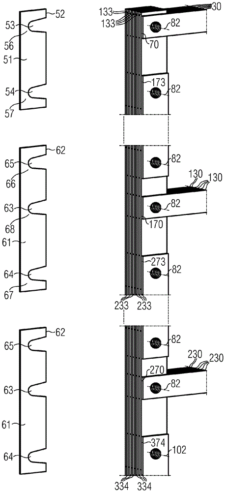
[0030] In order to transfer the electrical energy generated by the generator 7 to the power module 5 (which has different electrical units), in the inner space 8 of the tower 2 on the walls there are conductor rails 10 arranged with fixing elements 9, which are adjacent The joints of the tower sections are connected with flexible connecting rails. These conductor rails are electrically conductive and are electrically connected via cables 11 to the generator and via ...


PUM


Abstract

The invention relates to a device (50; 60) with a rigid connecting rail (51; 61) for electrically conductively connecting a first (30; 130; 230) to a second (133; 233; 334) conductor rail, which The contact flanks ( 70 ; 170 ; 270 , 173 ; 273 ; 374 ) extend parallel to each other and are connected to the connecting rails by means of first and second connecting means ( 80 , 80 ) respectively having connecting bolts ( 81 ) extending transversely to the contact flanks ( 51 ; 61 ) are held together under pressure, wherein each connecting rail ( 51 ; 61 ) contacts the contact flank ( 70 ; 170 ; 270 ) of one of the first conductor rails ( 30 ; 130 ; 230 ) in an electrically conductive manner The contact flank ( 173 ; 273 ; 374 ) has a first contact surface ( 56 ; 66 ) and has a second contact surface ( 57 ; 67 ) for conductive contact with one of the second conductor tracks ( 133 ; 233 ; 334 ). In order to make the connection of the first and second conductor rails easier, in particular when they are pre-assembled in a segment, for example a power module segment of a wind power installation, the connection rails ( 51 ; 61 ) are provided for connecting through The bolt ( 81 ) has a first ( 53 ; 63 ) and a second ( 54 ; 64 ) indentation open on one side on the side facing the connecting bolt ( 81 ), respectively.

Description

technical field [0001] The invention relates to the field of wiring and to the construction of a device with rigid connecting rails for the electrically conductive connection of first and second conductor rails, the contact sides of which extend parallel to each other, and which have respective transverse contact sides The first and second connecting means of the extended connecting bolts are fixed together with the connecting rails under pressure, wherein each connecting rail has a first contact surface for electrically conductive contact with the contact side of one of the first conductive rails and for electrically conductive The ground-contacting side of one of the second conductor tracks has a second contact surface. Background technique [0002] This device is known from document DE 42 02 783 A1, wherein a connecting rail is inserted between first and second conductor rails to be connected with opposite end faces, and then is electrically connected to the first and sec...

Claims


Application Information

Patent Timeline
Patent Type & Authority Patents(China)
IPC IPC(8): H02G3/04F03D1/00H02G5/04
CPCH02G3/0493H02G5/007
Inventor R.哈尔N.尼尔森
Owner SIEMENS AG
Features
  • R&D
  • Intellectual Property
  • Life Sciences
  • Materials
  • Tech Scout
  • Unparalleled Data Quality
  • Higher Quality Content
  • 60% Fewer Hallucinations
Learn More