
Ultrasonic diagnostic device

一种诊断装置、超声波的技术,应用在声波诊断、次声波诊断、超声波/声波/次声波诊断等方向,能够解决制冷剂泄漏、循环用泵、超声波探头表面温度保持等问题

Active Publication Date: 2011-10-19
TOSHIBA MEDICAL SYST CORP
View PDF5 Cites 3 Cited by
  • Summary
  • Abstract
  • Description
  • Claims
  • Application Information

AI Technical Summary

Problems solved by technology

However, in cables using soft and flexible hoses, etc., leakage of the refrigerant or failure of the circulation pump may easily occur. In such a case, the cooling capacity may decrease and the ultrasonic probe may not be connected The surface temperature remains within a safe range

Method used


Image

  • Ultrasonic diagnostic device
  • Ultrasonic diagnostic device
  • Ultrasonic diagnostic device

Examples


Embodiment Construction

[0024] Embodiments are described in detail with reference to the drawings.

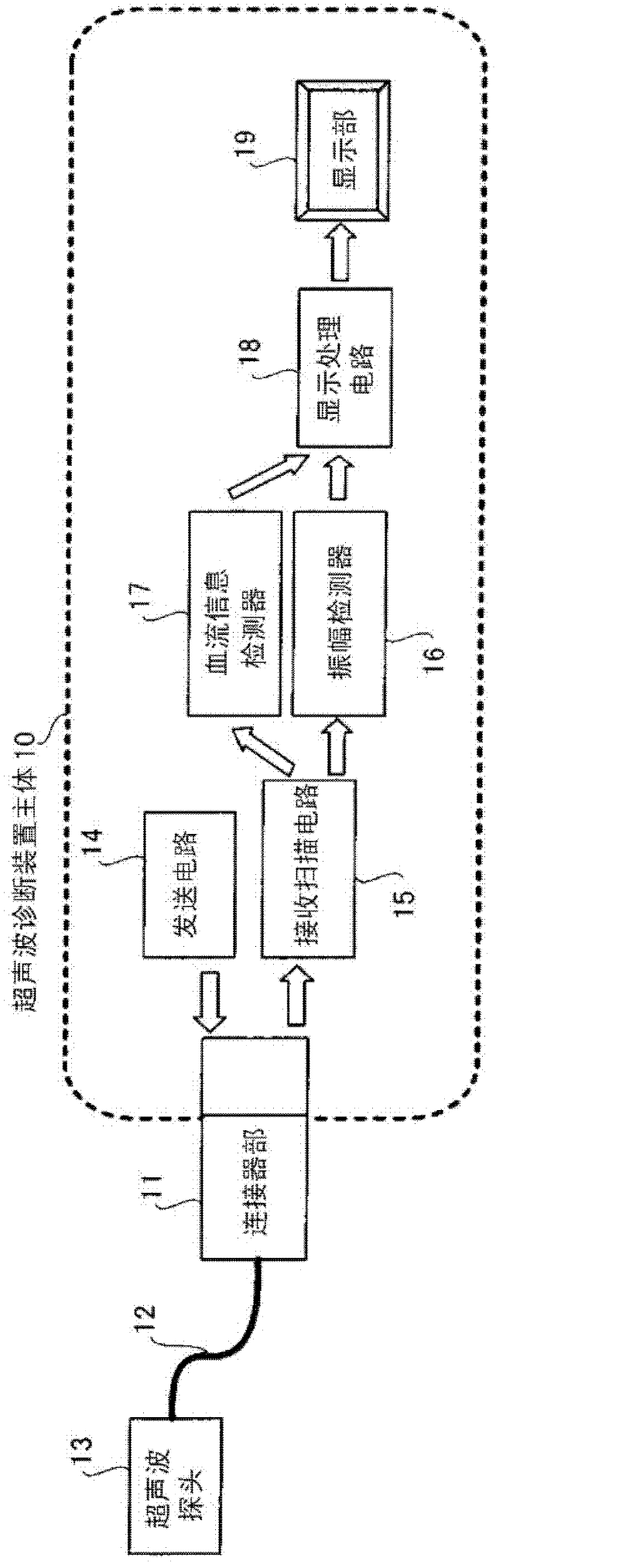
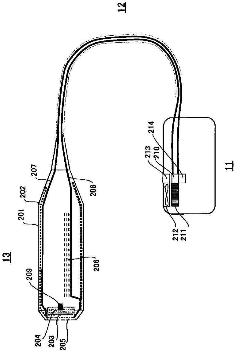
[0025] figure 1 It is a basic configuration diagram of an ultrasonic diagnostic apparatus according to an embodiment. The ultrasonic diagnostic apparatus main body 10 is used by connecting an ultrasonic probe 13 connected to a probe cable 12 via a connector portion 11 .

[0026] The main body 10 of the ultrasonic diagnostic apparatus has: a transmitting circuit 14 for generating ultrasonic waves from the ultrasonic probe 13; a receiving scanning circuit 15 for receiving ultrasonic signals reflected and returned from the subject; an amplitude detecting circuit 16 for generating tissue The morphology image; the blood flow analysis detector 17, which generates a blood flow Doppler image; the display processing circuit 18, which synthesizes the tissue morphology image and the blood flow Doppler image; and the display unit 19, which displays the synthesized image.

[0027] The ultrasonic probe 13 is inst...


PUM


Abstract

An ultrasonic diagnostic device is characterized by being provided with a cooling mechanism for cooling an ultrasonic vibrator by circulating a refrigerant in a cable of an ultrasonic probe in which the ultrasonic vibrator is provided, a cooling abnormality detecting means for detecting the abnormal state of the cooling mechanism, and an operating means for, when the abnormal state of the cooling mechanism is detected by the cooling abnormality detecting means, performing a degraded operation in which the transmission / reception condition of the ultrasonic vibrator is changed according to the detected abnormal state.

Description

technical field [0001] Embodiments of the present invention relate to an ultrasonic diagnostic apparatus. [0002] [Related application] [0003] This application is based on the priority of Japanese Patent Application No. 2009-149931 filed on June 24, 2009. The content of this Japanese application is hereby incorporated by reference into the present application. Background technique [0004] Among ultrasonic diagnostic devices capable of scanning three-dimensional images, devices configured to drive a two-dimensional array of ultrasonic vibrators by arranging a circuit inside the ultrasonic probe, and forming beams (beam forming) at the part to be observed are gradually becoming available. Be practical. Heat dissipation of such high-function, high-output, and high-density mounted ultrasonic probes has become an important technical issue. The ultrasonic probe cannot be sufficiently cooled by natural air cooling from the casing surface of the ultrasonic probe, so the ultr...

Claims


Application Information

Patent Timeline
Patent Type & Authority Applications(China)
IPC IPC(8): A61B8/00
CPCA61B8/00A61B8/06A61B8/44A61B8/4444A61B8/546
Inventor 宫岛泰夫
Owner TOSHIBA MEDICAL SYST CORP
Features
  • Generate Ideas
  • Intellectual Property
  • Life Sciences
  • Materials
  • Tech Scout
  • Unparalleled Data Quality
  • Higher Quality Content
  • 60% Fewer Hallucinations
Learn More