

Thermal by-pass valve with pressure relief capability
A technology of bypass valve and pressure relief valve, which is applied in the direction of function valve type, control of lubricant pressure, balance valve, etc., and can solve the problems of not setting pressure relief device, etc.
- Summary
- Abstract
- Description
- Claims
- Application Information
AI Technical Summary
Problems solved by technology
Method used
Image

Examples
Embodiment Construction
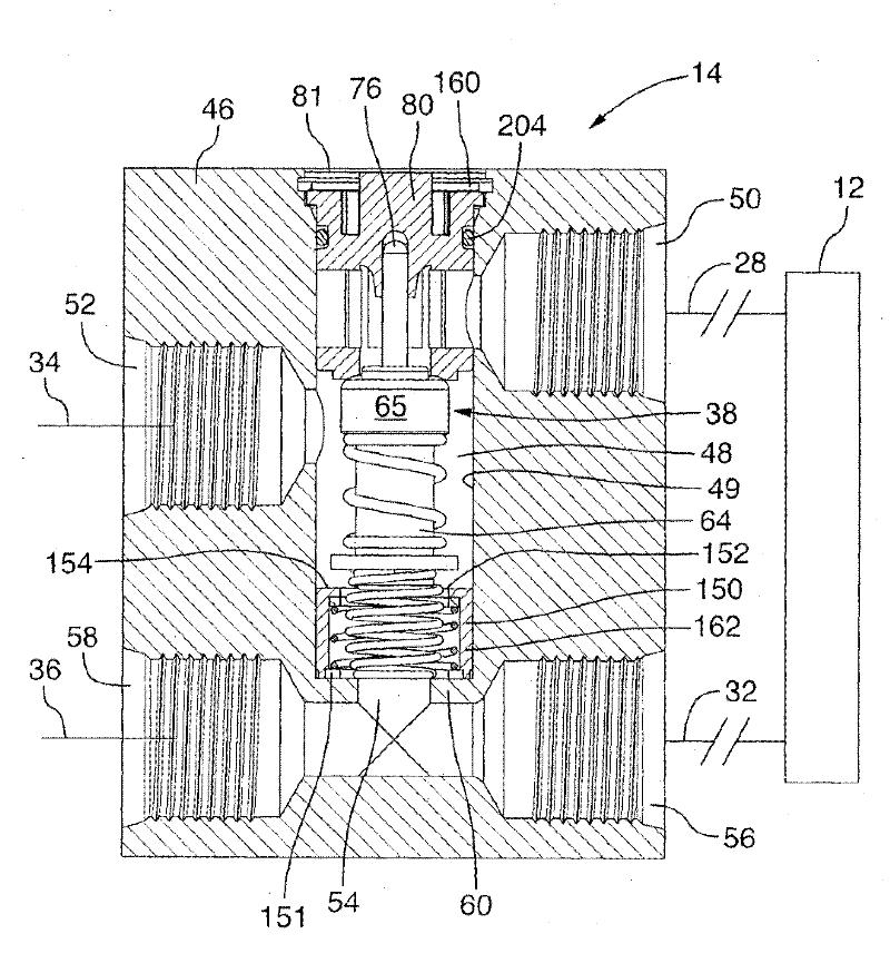
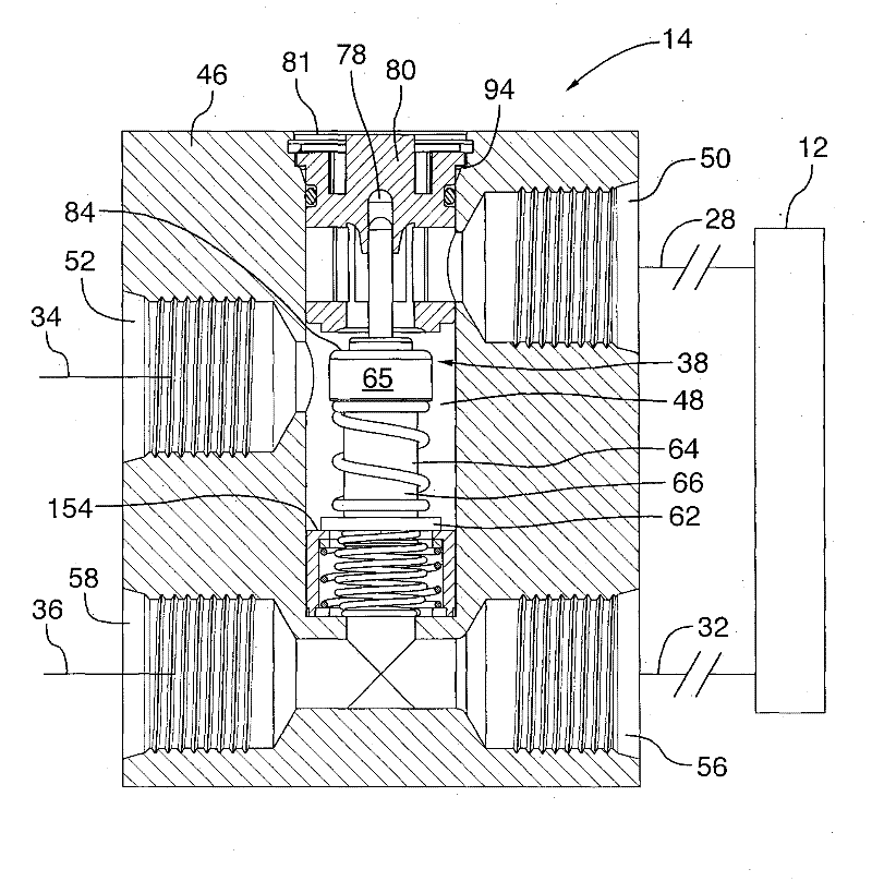
[0037] refer to figure 1 and 2 , shows an example of a bypass valve, generally indicated by reference numeral 14, which may be used in a heat exchanger circuit to control the flow of fluid, such as transmission fluid, to heat exchanger 12, which is connected to the first One and second conduits 28, 32 are connected. If the heat exchanger 12 is used to cool transmission fluid or oil, the heat exchanger may be a standard construction cooler or cooler unit. Conduits 28, 32 are connected to outlet port 50 and inlet port 56 of the valve. These ports may also be considered as orifice members connected to the valve chamber 48 for supplying and returning transmission fluid to the heat exchanger 12 . Conduits 34, 36 are also connected to ports 52, 58 in valve 14 and may be connected to vehicle components such as a transmission (not shown). Because the four conduits 28, 32, 34, 36 are connected to the valve, the valve 14 is referred to as a four-way bypass valve.
[0038] The valve...
PUM
 Abstract
Description
Claims
Application Information