Direct drive type servo knife rest

A servo tool holder and direct drive technology, applied in the direction of clamping, supporting, positioning devices, etc., can solve the problems of affecting machining accuracy, poor accuracy, easy shock and vibration, etc., to avoid transmission errors, improve reliability and The effect of precision

Active Publication Date: 2011-11-16
NORTHEASTERN UNIV
View PDF9 Cites 15 Cited by
  • Summary
  • Abstract
  • Description
  • Claims
  • Application Information

AI Technical Summary

Problems solved by technology

[0006] The paper "Design of Servo Toolpost Control System Based on DSP" mentioned a servo tool post, which is driven by a servo motor through a gear system to rotate the cutter head and realize the initial positioning of the cutter head. Acc

Method used


Image

  • Direct drive type servo knife rest
  • Direct drive type servo knife rest
  • Direct drive type servo knife rest

Examples


Embodiment Construction

[0023] The present invention will be further described below in conjunction with the accompanying drawings and embodiments.

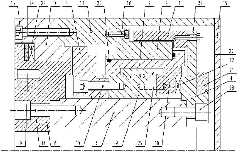
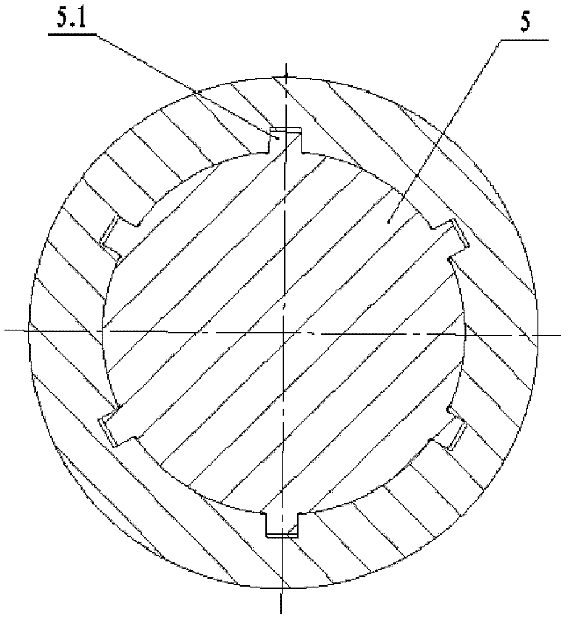
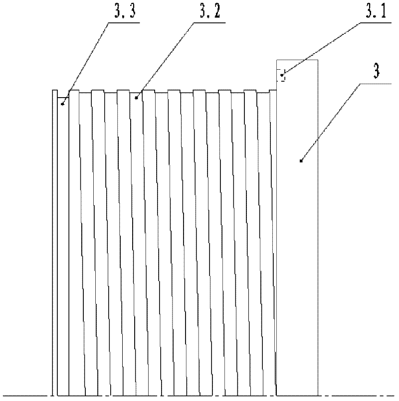
[0024] like figure 1 , figure 2 , image 3 As shown, the direct-drive servo tool post includes an outer shell 11, a torque motor, a disc connector 4, a main shaft 5, a movable toothed plate 6, a fixed toothed plate 7, and a locking toothed plate 8. The rear end of the outer shell 11 is provided with a rear End cover 19, the tool holder is directly driven by a low-speed, high-torque, outer rotor torque motor, the torque motor is located at the rear end of the tool holder, and the torque motor stator 2 passes through the bolt 16 is fixed on the outer casing 11, and the torque motor rotor 1 is fixed by bolts 22 is fixed with the disc connector 4, and the disc connector 4 passes through the bolt 13 is fixed to the rear end of the main shaft 5, and the circumferential positioning is realized through the spline 5.1 of the main shaft 5. The right end o...


PUM


Abstract

The invention discloses a direct drive type servo knife rest, which comprises an outer shell, a torque motor, a disc-shaped connecting piece, a main shaft, a movable toothed disc, a fixed toothed disc and a locking toothed disc. The knife rest is directly driven by the torque motor; the torque motor is located at the rear end of the knife rest; a torque motor stator is fixed on the outer shell through a screw bolt; a torque motor rotor is fixed with the rear end of the main shaft through the disc-shaped connecting piece; the moveable toothed disc is fixed with the front end of the main shaft;the fixed toothed disc is fixed on the outer shell through a screw bolt; and the locking toothed disc is sleeved on the main shaft and forms a triple toothed disc mechanism together with the movable toothed disc and the fixed toothed disc. The knife rest disclosed by the invention has the advantages of simple and compact structure, small occupied space, low maintenance cost, high transmission efficiency, smoothness in operating and low noise.

Description

technical field [0001] The invention belongs to the technical field of tool holders for numerically controlled machine tools, in particular to a direct-drive servo tool holder. Background technique [0002] Turning machining centers and turning-milling compound machining centers are important processing equipment in aviation, aerospace, military and other industrial fields. The CNC tool post is the core functional component of the turning machining center and the turning-milling compound machining center. Its performance and structure directly affect the cutting performance and cutting efficiency of the machine tool, reflecting the design and manufacturing level of the machine tool. The basic functions of the tool post: one is to fix the tool, and the other is to realize automatic tool change. According to the driving method for tool change, the tool post can be divided into manual tool post, electric tool post (common motor drive), hydraulic tool post (hydraulic motor driv...

Claims


Application Information

Patent Timeline
IPC IPC(8): B23Q3/157B23Q11/12
Inventor 张义民闫明杨周黄贤振史荣生
Owner NORTHEASTERN UNIV
Why Eureka
Try Eureka