Combined type LED (light emitting diode) road lighting lamp
A lighting fixture and a combined technology, which are applied to energy-saving lighting, lighting devices, fixed lighting devices, etc., can solve the problems of increased cost and reduced heat dissipation effect of LED light source module units.
- Summary
- Abstract
- Description
- Claims
- Application Information
AI Technical Summary
Problems solved by technology
Method used
Image

Examples
Embodiment Construction
[0016] A specific embodiment of the present invention will be described below in conjunction with the accompanying drawings.
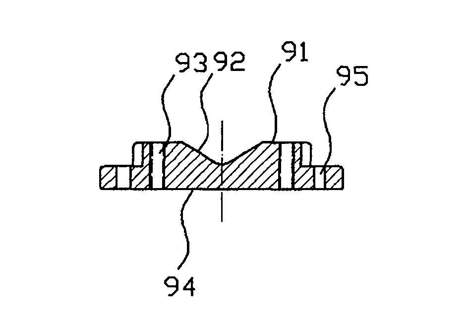
[0017] figure 1 is a schematic cross-sectional view of the connector.
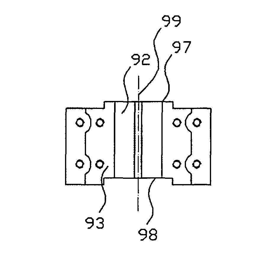
[0018] figure 2 is a schematic top view of the connector.
[0019] The connecting body is made of thermally conductive material, which may be aluminum or other materials with good thermal conductivity. The connecting body has an installation axis 99, and is provided with a mounting structure connected to the light pole or a light pole extension structure, a fixing structure connected to the carrying box, and a positioning structure for positioning adjacent to the connecting body. structure.
[0020] The installation structure is composed of a support platform 91 , a positioning groove 92 , and an installation threaded hole 93 . On the upper surface of the connecting body 1 , a support platform 91 is provided along the installation axis 99 , and the support platform 91 is used...
PUM
 Abstract
Description
Claims
Application Information
PatSnap Eureka turns technology decisions into work you can execute. Powered by our Innovation Knowledge Graph, it runs expert workflows across engineering, life sciences, materials and intellectual property. Get your review-ready output in minutes.


