Switches, especially load break switches for low voltage

A technology of switches and switch shafts, which is applied to the parts of protection switches, electric switches, protection switches, etc.

Inactive Publication Date: 2011-12-28
SIEMENS AG
View PDF4 Cites 0 Cited by
  • Summary
  • Abstract
  • Description
  • Claims
  • Application Information

AI Technical Summary

Problems solved by technology

The vent hole is therefore located near the back side of the switch, thereby creating the risk of arc discharges towards the rear wall

Method used


Image

  • Switches, especially load break switches for low voltage
  • Switches, especially load break switches for low voltage
  • Switches, especially load break switches for low voltage

Examples


Embodiment Construction

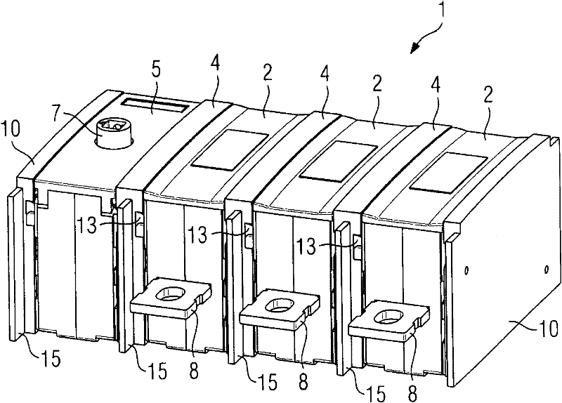
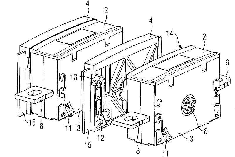
[0018] figure 1 A multipole switch 1 is shown, which has a substantially rectangular parallelepiped-shaped pole housing 2 for each phase. The side wall 3 of the electrode housing 2 (see figure 2 ) are arranged side by side side by side; the partition walls 4 are respectively located between these side walls 3 . based on figure 1 A control unit 5 is connected to the left of the three electrode housings 2, via which control unit the common switching shaft can be rotated about its longitudinal axis by means of a handle (not shown). The switching shaft consists of switching shaft section 6 (see figure 2 ) is formed and extends transversely through the side wall 3 of the electrode housing 2 . The handle is inserted into a corresponding recess of the drive shaft 7 cooperating with the switching shaft 6 for turning the switching shaft. The switching shaft can basically also be any other switching element for separating the contacts (contact pieces) for opening the switch 1 . ...


PUM


Abstract

The invention relates to a switch (1), in particular a load-break switch for low voltages, comprising: at least one rectangular parallelepiped-shaped electrode housing (2); a switch axis (6) transverse to the side walls ( 3) extending and separating the contacts against each other for opening the switch (1); and a through-hole (11) designed in the wall (3) of the electrode housing (2). In order to avoid the risk of arc discharge of electrons towards the rear wall, it is proposed to form a through hole (11) in the side wall (3), wherein a channel (12) is connected to the through hole, the channel in the discharge direction (16) of the end side The excess pressure that develops in the electrode housing (2) is discharged upwards.

Description

technical field [0001] The invention relates to a switch according to the preambles of claims 1 and 2 . Background technique [0002] DE 10 2005 007 301 A1 discloses a switch in which a movable contact piece is arranged in a rectangular parallelepiped-shaped housing, which bears against a fixed contact piece when the switch is switched on. The current flows through the two contact blocks, which are separated by means of the lever for opening the switch. The arc formed here is quenched by means of an arc quenching plate, which is arranged in the region of the contact block. The arc generates a high gas overpressure, which is conducted outwards via vent openings in the side walls of the housing. In order to prevent such gas from re-entering, vent openings with bends or deflections are provided. [0003] In another known load-break switch, the contact piece is arranged at the free end of a pivotable contact lever, which is often designed as a double lever. In multipole swit...

Claims


Application Information

Patent Timeline
Patent Type & Authority Applications(China)
IPC IPC(8): H01H9/34
CPCH01H2071/0285H01H2009/0094H01H19/02H01H9/342
Inventor 马蒂亚斯·埃斯纳
Owner SIEMENS AG
Why Eureka
Try Eureka