

Rotary joint locking device
A technology of rotating joints and locking devices, applied in the directions of manipulators, manufacturing tools, joints, etc., can solve the problems of excessive load at the end of the manipulator, failure of the locking mechanism, and insufficient load at the rotating joints, and achieves broad application prospects. , to solve the effect of locking failure
- Summary
- Abstract
- Description
- Claims
- Application Information
AI Technical Summary
Problems solved by technology
Method used
Image

Examples
Embodiment Construction
[0015] The specific embodiments of the present invention are given below with reference to the accompanying drawings, which are used to further describe the present invention.
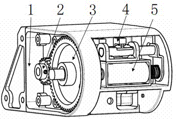
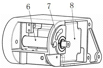
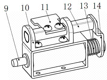
[0016] The rotary joint locking device of the present invention refers to the attached Figure 1-3 , including a rotary joint mechanism and a locking mechanism, the rotary joint mechanism includes a support 1 , a pinion 2 , a large gear 3 , a rotating shaft 6 , a copper sleeve 7 , and a motor 8 . A motor 8 is installed on the supporting member 1, and the two ends of the rotating shaft 6 are installed on the supporting member 1 through two copper sleeves 7. The coaxial large gear 3 is arranged on the rotating shaft 6, and the output shaft of the motor 8 is provided with The coaxial pinion 2, the bull gear 3 and the pinion 2 are meshed for transmission. The motor 8 drives the rotating shaft 6 to rotate through the deceleration of the bull gear 3 and the pinion 2 . A massage device is connected and fixe...
PUM
 Abstract
Description
Claims
Application Information