
Automatic locking clutch sheet

A clutch plate and automatic lock technology, applied in clutches, one-way clutches, mechanical equipment, etc., can solve problems such as sideslip, locked, uncontrollable, etc.

Inactive Publication Date: 2012-03-14
南通杨天机电设备有限公司
View PDF6 Cites 2 Cited by
  • Summary
  • Abstract
  • Description
  • Claims
  • Application Information

AI Technical Summary

Problems solved by technology

If the brake pedal is pressed hard while the vehicle is running, the wheel speed will drop rapidly. When the braking force exceeds the friction force between the wheel and the ground, the wheel will be locked. A completely locked wheel will make the friction force between the tire and the ground If the front wheels are locked, the driver cannot control the driving direction of the vehicle, and if the rear wheels are locked, it is very easy to slip

Method used


Image

  • Automatic locking clutch sheet
  • Automatic locking clutch sheet
  • Automatic locking clutch sheet

Examples


specific Embodiment 2

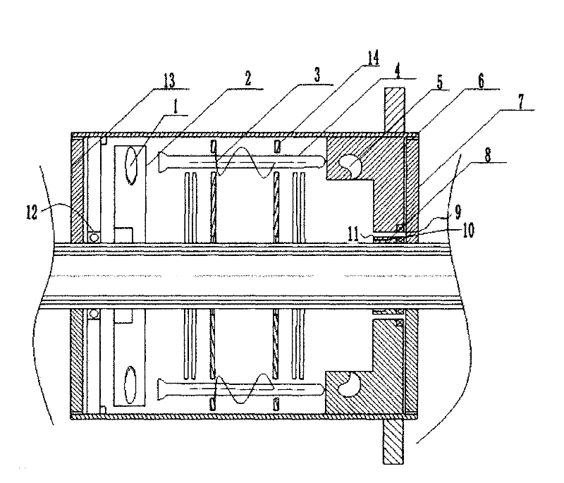
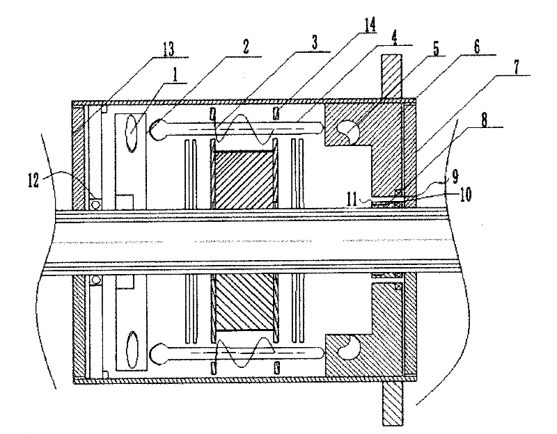
[0016] In order to further optimize the above-mentioned technical scheme, the following combination figure 2 For further explanation: First, for the convenience of installation, the first disc and the second disc are integrated, and one end of the spring is stuck on the first disc in advance, and then the lock pin is inserted along the hole, and the other end of the spring is provided with The lower hook slides along the lock pin into the locking hole of the lock pin. In this solution, the first disc and the second disc are connected as a whole, and there will be no inertia difference between the first disc and the second disc during operation, so that the operation of the entire clutch plate is more stable.

specific Embodiment 3

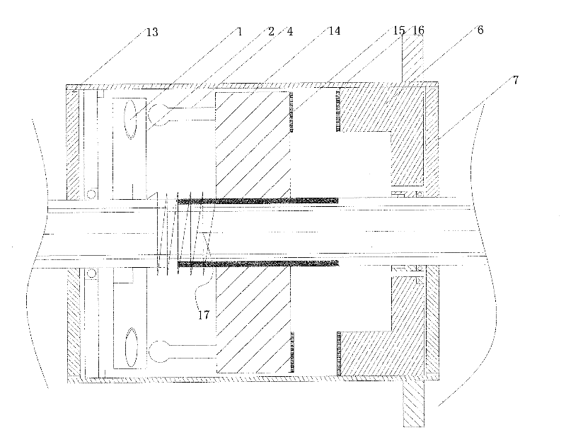
[0017] This embodiment provides another kind of implementation, below in conjunction with image 3 For further explanation; the method is to set a detour spring 17 between the lock pin placement plate and the rear push plate, and the front end of the lock pin placement plate is provided with an automatic locking passive one-way tooth, which is automatically locked with the active plate. One-way meshing is formed between the teeth. When the engine is running, the active one-way teeth on the driving disc squeeze the passive teeth from the deep to the shallow until the passive teeth are pushed out of the active teeth, and the lock pin placement plate passes through the sliding flower set between the drive shaft and the drive shaft. The keyway slides parallel to the direction of the rear push plate, so that the end of the lock pin is inserted into the pin seat on the rear push plate, forcing the detour spring to compress; when the driver steps on the brake, as above, under the act...


PUM


Abstract

The invention relates to a clutch sheet, in particular to a clutch sheet applied to the field of a clutch mechanism of a vehicle. The invention aims at providing the clutch sheet capable of completing that the one-way function of the clutch sheet is closed while an owner steps on a brake; and when the owner throttles up the engine or loosens a throttle, the clutch sheet automatically realizes theone-way function. In order to the purpose, the automatic locking clutch sheet comprises a one-way gear, an automatic lock and a lock pin placement disk, wherein the one-way gear is fixed on a transmission main shaft through a half-interval fixture block, the automatic lock is arranged inside the clutch sheet at the rear end of the one-way gear, the automatic lock is fixed on the transmission mainshaft through the lock pin placement disk, and the lock pin is connected with a drive disk integrated with the one-way gear.

Description

technical field [0001] The invention relates to a clutch plate, in particular to a clutch plate design applied in the field of clutch mechanisms of vehicles. Background technique [0002] The rotational power generated by the existing vehicle engine when starting is transmitted to the wheels by the transmission system, and the wheels drive the vehicle to advance through rotation. In the transmission system, a clutch structure is set between the engine power output end and the gearbox. The structure includes a clutch disc and a clutch disc. A pressure plate is set in the clutch disc. The clutch disc is set on the transmission shaft of the power output. The clutch disc is set on the power output end of the engine. The pressure plate in the clutch disc can press On the clutch plate, the pressure plate and the clutch plate can be press-contacted by the friction force, or the clutch action of separation from each other, so that the output power of the engine can be transmitted to...

Claims


Application Information

Patent Timeline
Patent Type & Authority Applications(China)
IPC IPC(8): F16D41/04
Inventor 郭富
Owner 南通杨天机电设备有限公司
Learn More