
Medical transfusion switch

A switch and switch cover technology, which is applied in the direction of hypodermic injection devices, etc., can solve the problems that patents and non-patent literature have not seen technical inspiration and other issues

Active Publication Date: 2012-12-05
CONOD MEDICAL
View PDF4 Cites 0 Cited by
  • Summary
  • Abstract
  • Description
  • Claims
  • Application Information

AI Technical Summary

Problems solved by technology

[0002]As is well known in the industry, the infusion pipeline is usually equipped with an infusion switch. There are generally two structures of the infusion switch: one is push block or pressure wheel structure , this kind of switch is prone to swimming phenomenon under slight touch; the second is the dial-type infusion switch with a 90° rotation angle, this kind of infusion switch will not change due to slight touch, but in the actual use process There are still deficiencies, especially at night, if the patient or the accompanying person fails to turn the switch to 90°, then the infusion tube will be cut off, that is, there will be no fluid flow
Again, for the weak, such as those who are bedridden for a long time, the disabled, etc., it is often difficult to correctly turn the dial to the degree of 90 ° due to lack of physical strength.
[0003] In view of the above, it is necessary to improve the structure of the infusion switch of the dial type in the prior art. For this reason, the applicant has done a literature search, but in There are no technical inspirations that can be used for reference in published patents and non-patent literature

Method used


Image

  • Medical transfusion switch

Examples


Embodiment Construction

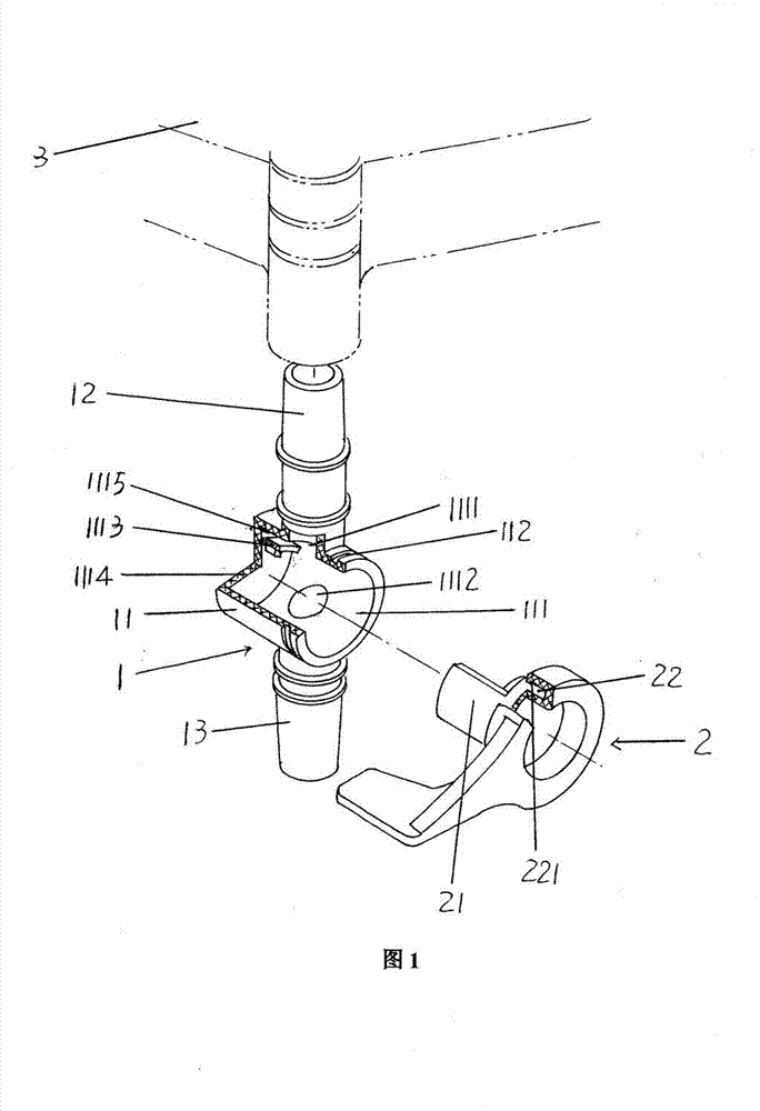
[0009] Please see figure 1 , a switch body 1 is given, the switch body 1 is composed of a switch sleeve 11, a liquid inlet joint 12 and a liquid outlet joint 12, and a liquid inlet hole 1111 and a liquid outlet hole 1112 are opened on the cavity 111 of the switch sleeve 11 , the liquid inlet and outlet holes 1111, 1112 are separated from each other by 180° in the circumferential direction of the switch sleeve 11, the liquid inlet joint 12 directly extends on the switch sleeve 11 and corresponds to the aforementioned liquid inlet hole 1111, and the liquid outlet joint 13 is also directly formed It is on the switch cover 11 and corresponds to the aforementioned liquid outlet hole 1112 . An arc-shaped support plate 1113 is formed on the cavity bottom plate 1114 of the cavity 111, and the arc-shaped support plate 1113 corresponds to the position of the liquid inlet hole 1111, and is between the top of the arc-shaped support plate 1113 and the wall of the cavity 111 A distance ...


PUM


Abstract

The invention relates to a medical transfusion switch, which belongs to the technical field of medical equipment and comprises a switch body and a poking handle, wherein the switch body comprises a switch sleeve, a liquid inlet joint and a liquid outlet joint, the switch sleeve is provided with a cavity, the cavity is provided with a liquid inlet hole and a liquid outlet hole, the liquid inlet joint is directly formed on the switch sleeve and is corresponding to the liquid inlet hole, the liquid outlet joint is directly formed on the switch sleeve and is corresponding to the liquid outlet hole, the poking handle is matched with the switch sleeve in a rotating mode, and the poking handle is provided with an arc-shaped sealing plate. The medical transfusion switch is characterized in that an arc-shaped supporting plate is arranged in the cavity and in the position corresponding to the liquid inlet hole, the arc-shaped supporting plate is formed on the bottom plate of the cavity, a sealing plate rotating groove is maintained above the arc-shaped supporting plate, the arc-shaped sealing plate is matched with the sealing plate rotating groove, a central line of the liquid inlet joint and an axial central line of the cavity are not in the same plane, one side of the poking handle, which faces the switch sleeve, is provided with a poking handle pivoting groove, and the poking handle pivoting groove is matched with the switch sleeve.

Description

Technical field [0001] The invention is a medical equipment technology field, which involves a medical infusion switch. Background technique [0002] As known in the industry, there are usually two types of infusion switches on the infusion pipeline, and the structure of the infusion switch is roughly two: one is to push the block or pressure wheel structure. This switch is easy to swim under slight touch;Second, a handlebar infusion switch with a 90 ° rotation angle angle, this infusion switch will not change due to slight touch, but in the actual use process, it is still exposed, especially at night, the patient itself or the accompanying staffFailure to transfer the switch to 90 °, then the infusion pipe is broken, that is, no liquid.In addition, for those who are weak, such as chronic diseases, people with disabilities, etc. Due to their physical strength, it is often difficult to transfer the degree of correctly to 90 °. [0003] In the book, it is necessary to improve the s...

Claims


Application Information

Patent Timeline
Patent Type & Authority Patents(China)
IPC IPC(8): A61M5/175
Inventor 朱建新
Owner CONOD MEDICAL
Learn More