
Electronic equipment capable of regulating light-emitting rate

A technology for electronic equipment and astigmatism, which is applied in mechanical equipment, lighting and heating equipment, optics, etc., and can solve problems such as affecting the publicity or sales effect of electronic equipment, and single brightness of trademark logos.

Inactive Publication Date: 2012-03-28
HONG FU JIN PRECISION IND (SHENZHEN) CO LTD +1
View PDF0 Cites 0 Cited by
  • Summary
  • Abstract
  • Description
  • Claims
  • Application Information

AI Technical Summary

Problems solved by technology

[0002] In electronic equipment, LEDs (light-emitting diodes) are often used to illuminate the trademark logo on the product, and the trademark logo shows a single brightness
When electronic equipment is exhibiting or selling, if the ambient light is too bright and the brightness of the trademark on the electronic equipment is not enough, the trademark will be ignored by people, which will affect the promotion or sales effect of electronic equipment

Method used


Image

  • Electronic equipment capable of regulating light-emitting rate
  • Electronic equipment capable of regulating light-emitting rate
  • Electronic equipment capable of regulating light-emitting rate

Examples


Embodiment Construction

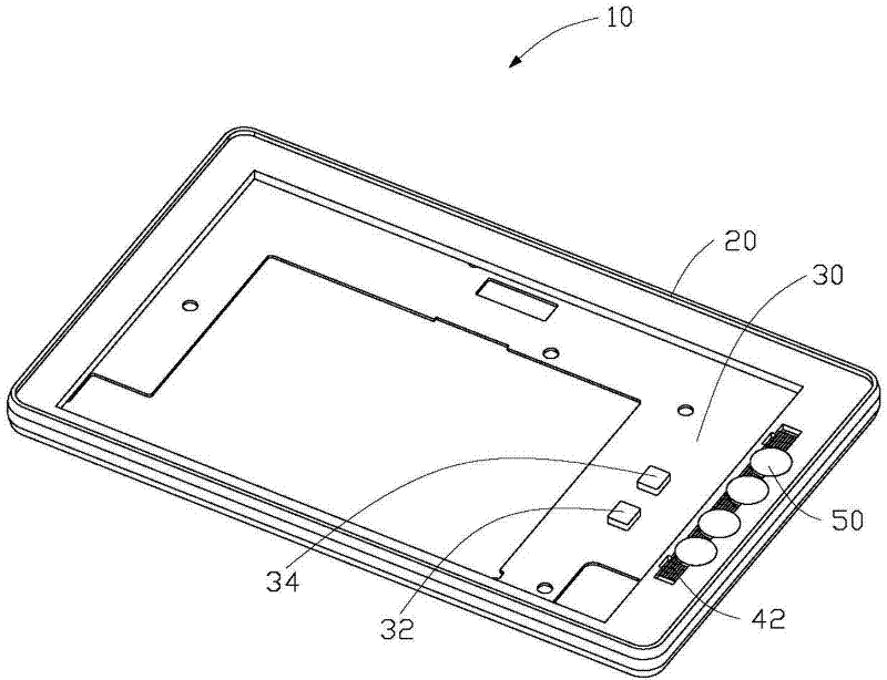
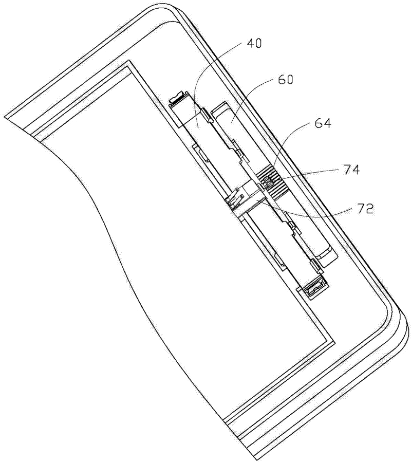
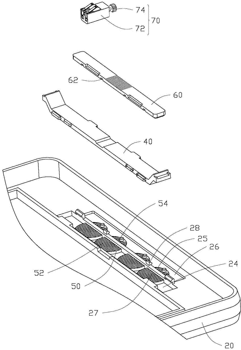
[0012] Please also see Figure 1 to Figure 3 , the electronic device 10 includes a casing 20 , a circuit board 30 , a transparent light guide plate 40 , a plurality of transparent diffusers 50 , a transmission member 60 and a drive member 70 . The circuit board 30 is fixed in the casing 20 and is electrically connected with a light emitting element (not shown in the figure). The light guide plate 40 is placed between the circuit board 30 and the diffuser 50 , the light emitted by the light-emitting element is incident on the diffuser 50 through the light guide 40 , and the surface of the light guide 40 facing the diffuser 50 is formed with concave-convex lines 42 . The diffuser 50 is rotatably disposed on the casing 20 and kept at a certain distance from the circuit board 30 , and the surface of the diffuser 50 facing the light guide plate 40 is formed with concave-convex lines 52 . The driving member 70 is electrically connected to the circuit board 30, and is used to drive ...


PUM


Abstract

The invention relates to electronic equipment, in particular to the electronic equipment capable of regulating the light-emitting rate, which comprises a shell, a circuit board, a transparent light-diffusing piece, a transmission part and a driving part, wherein the circuit board is fixedly arranged on the shell. A luminous element is electrically connected onto the circuit board. The light-diffusing piece is rotatably arranged on the shell, and concave and convex grains are formed on the surface of the light-diffusing piece. The transmission part is rotatably connected with the light-diffusing piece. A light sensor for sensing the brightness of external environmental light and a processor are also electrically connected onto the circuit board. The driving part is electrically connected to the circuit board. The processor is used for controlling the driving part to move according to the sensed brightness of the environmental light. The transmission part is driven to move by the driving part under the control of the processor, so that the light-diffusing piece is driven to rotate by the driving part to further change the positions of the concave and convex grains to regulate the light-emitting rate of the light emitted by the luminous element passing through the light-diffusing piece. The light-emitting rate of the light passing through the light-diffusing piece can be regulated by changing the positions of the concave and convex grains of the light-diffusing piece through the electronic equipment.

Description

technical field [0001] The invention relates to an electronic device, in particular to an electronic device capable of adjusting the output rate of light. Background technique [0002] In electronic equipment, LEDs (light-emitting diodes) are often used to illuminate the trademark logo on the product, and the trademark logo displays a single brightness. When the electronic equipment is exhibiting or selling, if the ambient light is too bright and the brightness of the trademark on the electronic equipment is not enough, the trademark will be ignored by people, which will affect the promotion or sales effect of the electronic equipment. Contents of the invention [0003] In view of this, the present invention provides an electronic device capable of adjusting the output rate of light. [0004] An electronic device includes a shell, a circuit board fixed on the shell, a transparent diffuser, a transmission part and a drive part. A light emitting element is electrically con...

Claims


Application Information

Patent Timeline
Patent Type & Authority Applications(China)
IPC IPC(8): F21V14/04F21V8/00
CPCG02B6/005
Inventor 肖双红杨和辉吴开贵谢坤智
Owner HONG FU JIN PRECISION IND (SHENZHEN) CO LTD
Learn More