
Integrated light path device capable of detecting and controlling light intensity

A technology for controlling light and detecting light. It is used in measuring devices, using electrical radiation detectors for photometry, optics, etc., to solve problems such as inability to achieve effective detection, and achieve excellent anti-slip effect, consistent rotation angle, and coaxiality. high effect

Pending Publication Date: 2021-11-09
SHENZHEN TECH UNIV
View PDF0 Cites 0 Cited by
  • Summary
  • Abstract
  • Description
  • Claims
  • Application Information

AI Technical Summary

Problems solved by technology

[0004] The purpose of the present invention is to solve the problems existing in the prior art that the effective detection of different bands from ultraviolet to near-infrared and the modulation of optical power output cannot be realized, and a kind of optical path that can detect and control light intensity is proposed device

Method used


Image

  • Integrated light path device capable of detecting and controlling light intensity
  • Integrated light path device capable of detecting and controlling light intensity
  • Integrated light path device capable of detecting and controlling light intensity

Examples


Embodiment 1

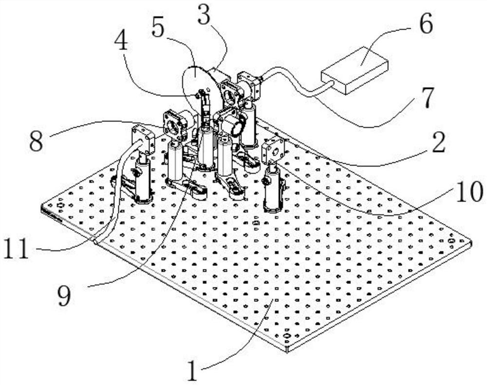
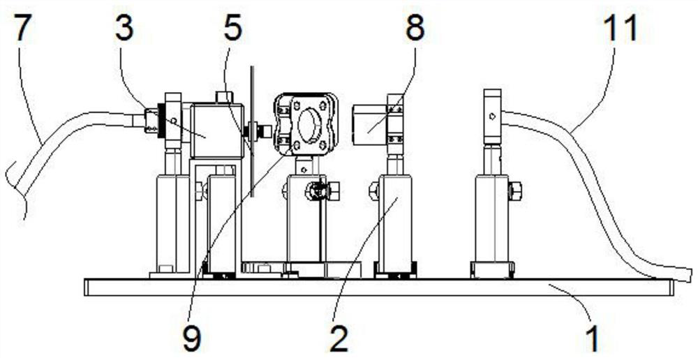
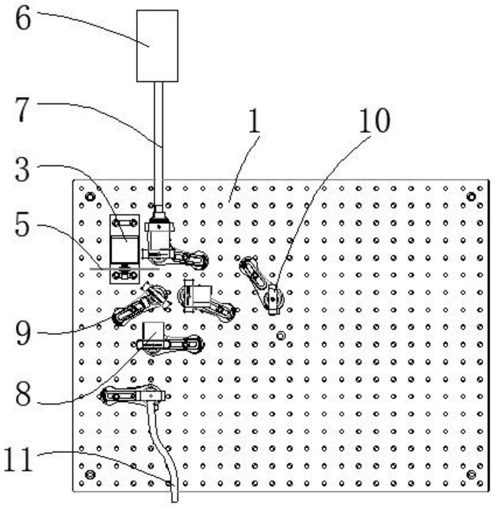
[0053] see Figure 1-3 , this embodiment provides an optical circuit device capable of detecting and controlling light intensity, which is used for modulating the output power of light. The optical path device includes an operating table 1, at least eight sets of support bodies 2 fixedly installed on the operating table 1, a stepping motor 3 arranged on the operating table 1, a fixed assembly 4 arranged on the stepping motor 3, a movable assembly installed on the stepping Filter wheel 5 on the input motor 3, laser 6, input optical fiber 7, three groups of plano-convex lenses 8, beam splitter 9, photodiode 10, output optical fiber 11, single-chip microcomputer and photoelectric detection module.

[0054] The stepper motor 3 , laser 6 , input optical fiber 7 , plano-convex lens 8 , beam splitter 9 , photodiode 10 and output optical fiber 11 are all fixedly installed on the corresponding supporting body 2 . The stepping motor 3 , laser 6 , input optical fiber 7 , plano-convex le...

Embodiment 2

[0062] see Figure 7 , this embodiment provides a method for controlling light intensity, which is applied to the optical circuit device that can detect and control light intensity as in Embodiment 1. The steps of the light intensity control method are as follows:

[0063] S1 provides an optical path device, which is equipped with light intensity and optical path control software.

[0064] S2 inputs the required target light intensity, and the optical path device converts to obtain the voltage signal value corresponding to the target light intensity;

[0065] The user manually inputs the required target light intensity, and the input value is received by the light intensity and optical path control software written by the labview software, and the corresponding voltage signal value is calculated according to the previous database and function ratio.

[0066] The voltage signal value is calculated according to the database and function ratio. The calculation formula is: volt...


PUM


Abstract

The invention discloses an integrated light path device capable of detecting and controlling light intensity. The optical path device comprises an operation table, at least eight groups of supporting bodies fixedly mounted on the operation table, a stepping motor arranged on the operation table, a fixing assembly arranged on the stepping motor, a filter wheel movably mounted on the stepping motor, a laser, an input optical fiber, an output optical fiber, three groups of plano-convex lenses, a beam splitter; and a photodiode. The fixing assembly comprises a first spring fixedly installed on the stepping motor, a pedestal fixedly connected with the first spring, a gasket connected to the pedestal in a clamped mode, a second spring and a sleeve head. According to the optical path device, light intensity detection and control are integrated, effective detection of different wave bands from ultraviolet to near infrared and modulation of light power output are achieved, the coaxiality of the rotating shaft of the filter wheel and the rotating shaft of the stepping motor are high, rotation angles are matched, the anti-eccentricity and anti-sliding effects of the filter wheel are excellent, and the light intensity adjustment, control and output accuracy of the optical path device is high.

Description

technical field [0001] The invention relates to the technical field of photoelectric detection, in particular to an optical path device capable of integrating detection and control of light intensity. Background technique [0002] In information technology, photoelectric sensing technology is an extremely important sensing technology. At present, the light source related to photoelectric detection is controlled by the light source power of a specific wavelength and specific band, and the light intensity detection is also independent. The unit price of a system is relatively high, and the existing multi-band detection is often used to measure the full-band spectral transmittance and reflectance of materials, and there is still a shortage in the integration of multi-band continuous optical power detection and regulation. [0003] The current optical device needs to be equipped with an independent light intensity detection system for detection, and it cannot realize effective d...

Claims


Application Information

Patent Timeline
IPC IPC(8): G01J1/42G01J1/04G02B26/00
CPCG01J1/42G01J1/0403G01J1/0414G01J1/0407G02B26/008Y02B20/40
Inventor 季涛韩全华许小杰黄扬易王俊睿邓兴广缪晓强
Owner SHENZHEN TECH UNIV
Learn More