Light beam universal extending system

A beam expansion system and beam technology, applied in optics, optical components, instruments, etc., can solve the problems of increased debugging time and cost, and achieve the effect of simple components, easy processing, and large adjustment range

Inactive Publication Date: 2005-05-11
SHANGHAI INST OF OPTICS & FINE MECHANICS CHINESE ACAD OF SCI
View PDF0 Cites 17 Cited by
  • Summary
  • Abstract
  • Description
  • Claims
  • Application Information

AI Technical Summary

Problems solved by technology

This will increase the debugging time and increase the cost

Method used


Image

  • Light beam universal extending system
  • Light beam universal extending system

Examples


Embodiment Construction

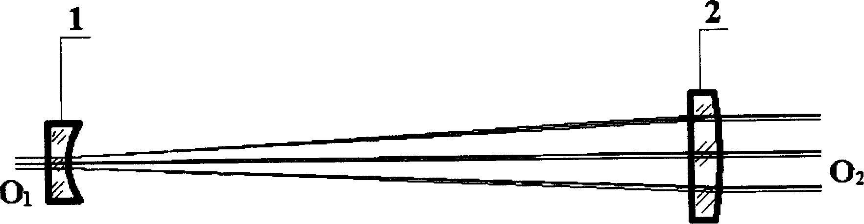
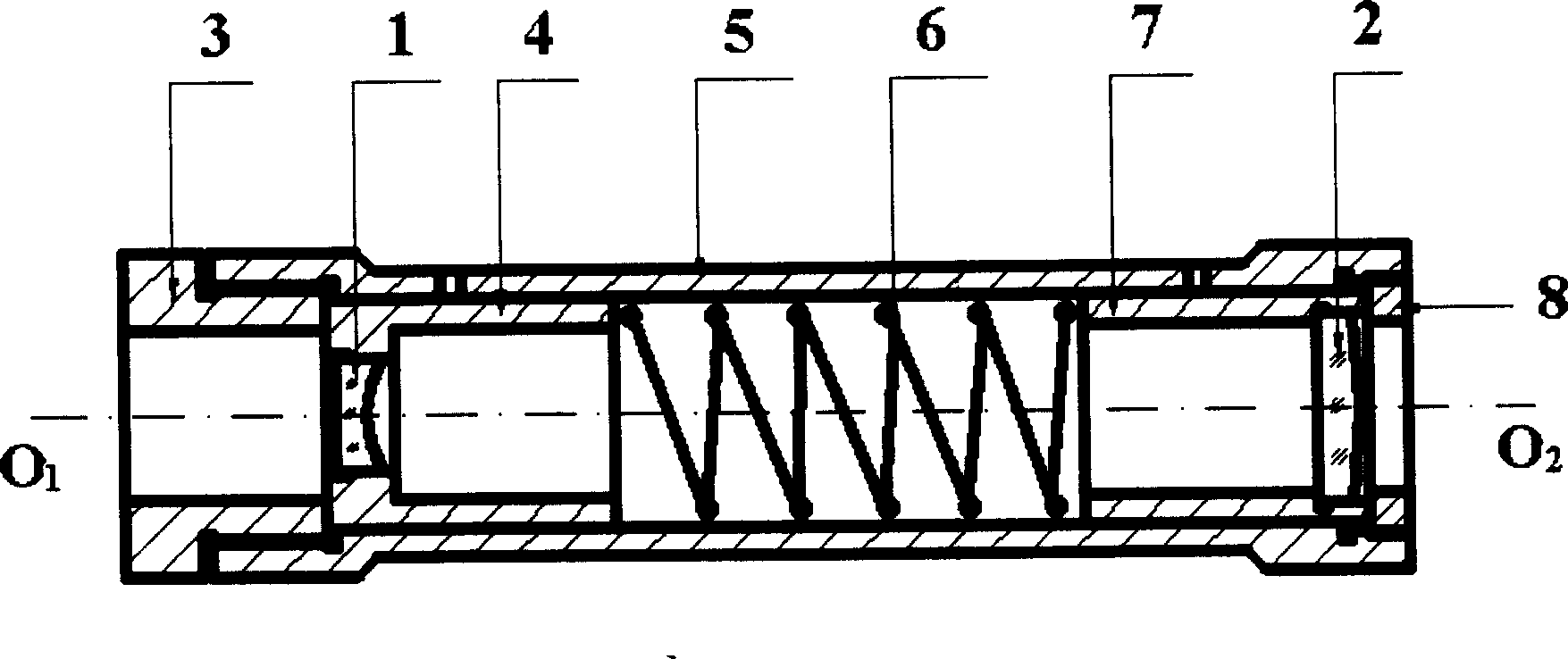
[0027] see first figure 1 and figure 2 , figure 2 It is the best schematic diagram of the structure of the best embodiment of the universal beam expander system of the present invention. It can be seen from the figure that the universal beam expander system of the present invention includes a beam expander negative mirror 1 and a beam expander positive mirror 2, and is characterized in that there is also a lens barrel 5. Inside the lens barrel 5, along the optical axis O 1 o 2 Sequentially be provided with adjusting handwheel 3, beam expanding negative mirror 1, negative mirror frame 4, spring 6, positive mirror frame 7, beam expanding positive mirror 2 and pressure ring 8, described negative mirror frame 4 and positive mirror frame 7 are connected with mirror The barrels 5 are closely matched, the spring 6 pushes the negative mirror frame 4 and the positive mirror frame 7, and the adjustment handwheel 3 and the lens barrel 5 are connected by threads. The pressure ring 8...


PUM


Abstract

An universal extender system of light beam consists of extender negative mirror and extender positive mirror. The system is featured as having a mirror tube with regulation handwheel, extender negative mirror, negative mirror frame, spring, positive mirror frame, extender positive mirror and pressing ring setting in sequence along light axis O1O2 in the mirror tube; coordinating the mirror frames closely with mirror tube, pushing against the mirror frames by spring and connecting handwheel to mirror tube with thread.

Description

Technical field: [0001] The invention relates to beam conversion, in particular to a universal beam expander system suitable for multiple beam expander ratios. technical background: [0002] In modern optical systems, it is often necessary to transform parallel beams of different calibers. In particular, the beam diameter of the ordinary laser output is generally relatively small, between 1-10mm, and it is usually necessary to expand the beam in the actual system to meet the actual needs. For example, in some optical storage systems, the diameter of the beam output by the laser is about 2mm. In order to make full use of the advantages of the large numerical aperture of the optical system in the optical storage system to minimize the focused spot, it is necessary to expand the beam to a large enough diameter (about 12mm). [0003] At present, the common beam expander system is usually aimed at a specific application, and there is only one beam expander ratio, and it is diff...

Claims


Application Information

Patent Timeline
Patent Type & Authority Applications(China)
IPC IPC(8): G02B7/02G02B27/09
Inventor 周飞徐文东干福熹
Owner SHANGHAI INST OF OPTICS & FINE MECHANICS CHINESE ACAD OF SCI
Why Eureka
Try Eureka