
Universal ultrasonic-assisted inner jetted dielectric electric discharge machining (EDM) milling tool head and manufacturing method thereof

An ultrasonic-assisted and electric spark technology, applied in the mechanical field, can solve problems such as low system speed, high friction resistance of rubber rings, and difficulty in ensuring coaxiality, and achieve the effects of reducing friction resistance, increasing rotation speed, and strong versatility

Inactive Publication Date: 2014-07-16
SHANDONG UNIV
View PDF5 Cites 18 Cited by
  • Summary
  • Abstract
  • Description
  • Claims
  • Application Information

AI Technical Summary

Problems solved by technology

The ultrasonic-assisted electric spark milling spindle head can realize the liquid and ventilation of the electrode, but there are the following problems: first, the ultrasonic horn is only positioned by the flange, and the coaxiality is difficult to guarantee; second, the horn side and the The center hole is inserted into a cavity through the upper and lower rubber sealing rings. The cavity is stationary and the horn rotates. The pressure gas or liquid flows into the cavity through the side of the horn and the center hole, and finally from the tool electrode. outflow, the frictional resistance of the rubber ring to the horn is large, resulting in a low speed of the whole system; the third is that the tool electrode is connected to the bottom end of the horn through threads, and the tool electrode needs to be specially prepared

Method used


Image

  • Universal ultrasonic-assisted inner jetted dielectric electric discharge machining (EDM) milling tool head and manufacturing method thereof
  • Universal ultrasonic-assisted inner jetted dielectric electric discharge machining (EDM) milling tool head and manufacturing method thereof
  • Universal ultrasonic-assisted inner jetted dielectric electric discharge machining (EDM) milling tool head and manufacturing method thereof

Examples


Embodiment Construction

[0032] The technical scheme of the present invention will be described in detail below in conjunction with the accompanying drawings.

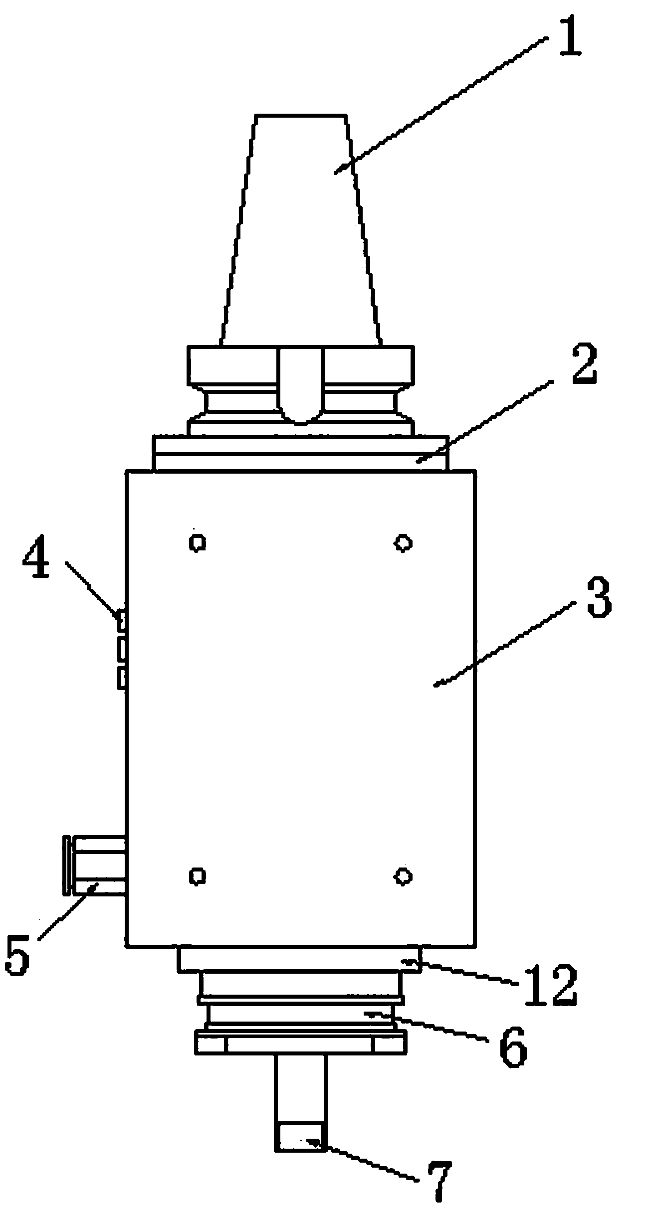
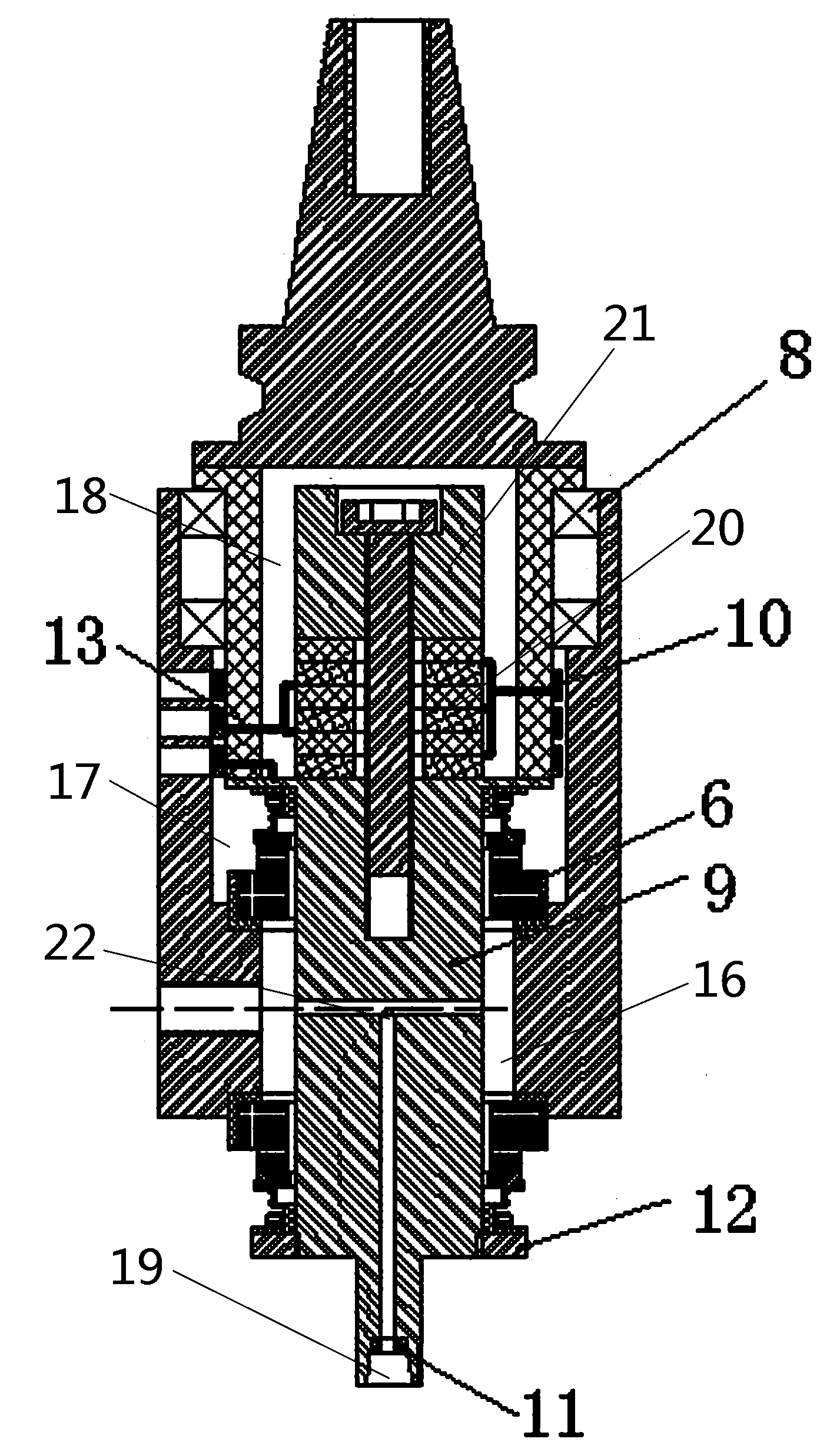
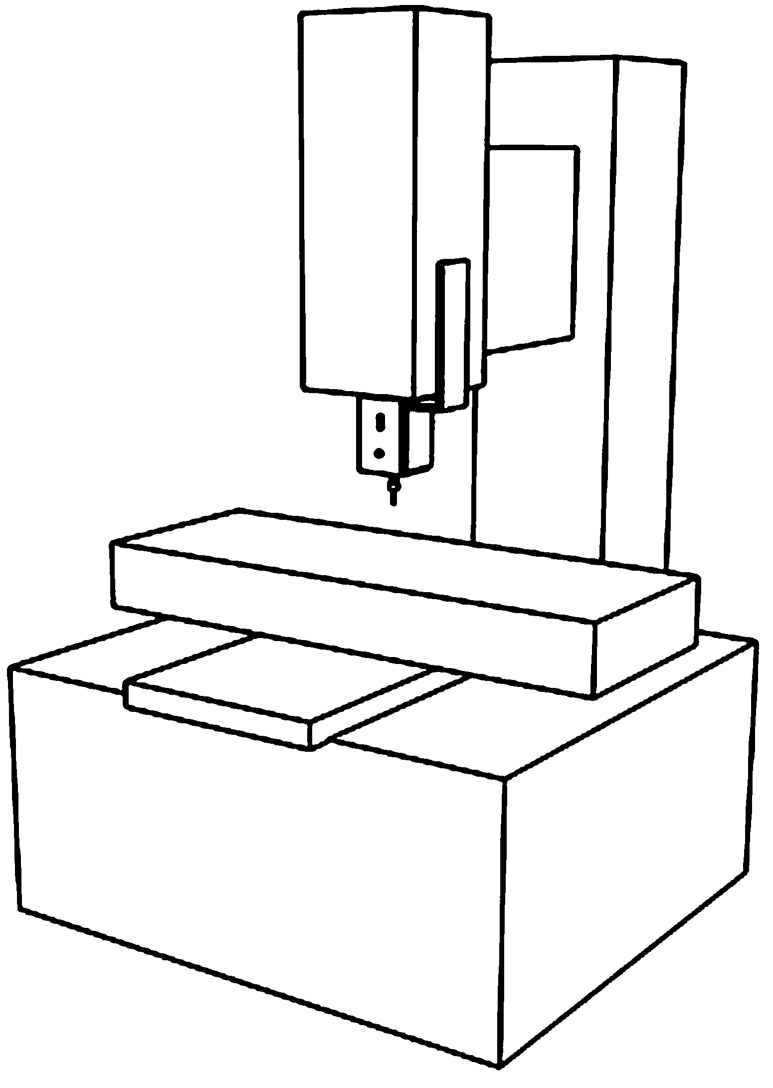
[0033] Such as Figure 1 to Figure 4 As shown, a general-purpose ultrasonic-assisted internal flushing EDM tool head of the present invention includes an ultrasonic vibration part, and also includes a tool handle 1 and a tool bar 7. The tool handle 1 is fixedly connected with an inner sleeve 2, and the inner sleeve 2 is fixed. Connected with a horn 9, the bottom end of the horn 9 is provided with a knife bar 7, and an electrode 15 is installed on the knife bar 7, the axes of the knife handle 1, the horn 9, and the knife bar 7 coincide, and the inner sleeve 2 is provided with a Outer jacket 3, outer jacket 3 extends to the middle section of horn 9, a cavity III16 is formed between outer jacket 3 and horn 9, a mechanical water seal 6 is provided at the end of cavity III 16, and a discharge medium is arranged inside the horn 9 Circulation channe...


PUM

PropertyMeasurementUnit
thicknessaaaaaaaaaa

Abstract

The invention relates to the field of machinery, in particular to a universal ultrasonic-assisted inner jetted dielectric electric discharge machining (EDM) milling tool head. The universal ultrasonic-assisted inner jetted dielectric EDM milling tool head comprises an ultrasonic vibration portion, a knife handle and a knife bar. The knife handle is fixedly connected with an inner sleeve. The inner sleeve is fixedly connected with an amplitude-change pole. The bottom end o the amplitude-change pole is provided with the knife bar. An electrode is installed on the knife bar. The axis of the knife handle, the axis of the amplitude-change pole and the axis of the knife bar are coincident. An outer sleeve is arranged outside the inner sleeve and extends to the middle section of the amplitude-change pole. A cavity III is formed between the outer sleeve and the amplitude-change pole. The end of the cavity III is provided with a mechanical water seal. The interior of the amplitude-change pole is provided with a discharge medium circulating channel. The universal ultrasonic-assisted inner jetted dielectric EDM milling tool head has the advantages of being high in coaxiality, high in rotational speed and simple in structure.

Description

technical field [0001] The invention relates to the field of machinery, in particular to a general-purpose ultrasonic-assisted internal flushing liquid electric spark milling tool head and a manufacturing method thereof. Background technique [0002] Ultrasonic vibration is essentially a mechanical vibration with small displacement and high frequency, usually a few microns to hundreds of microns, and above 20KHz. It is widely used because of its characteristics of cavitation, suspension, reflection, refraction, energy transmission and signal transmission. In the field of EDM, superimposing ultrasonic vibration on workpieces or tools for EDM has achieved good results in the field of micro-EDM. It has been proved that ultrasonic vibration can help improve the discharge frequency of micro-EDM and improve Discharge conditions promote the discharge of electro-corrosion products, and ultimately improve the processing effect and efficiency; in general EDM, ultrasonic vibration has ...

Claims


Application Information

Patent Timeline
Patent Type & Authority Applications(China)
IPC IPC(8): B23H7/38
Inventor 张敏张勤河
Owner SHANDONG UNIV
Learn More