Power-assisted bicycle including regenerative mechanism

一种电动辅助、自行车的技术,应用在机械设备、车辆部件、车辆变速箱等方向,能够解决传递、车轮反向输入无法、无法利用中心马达旋转、再生等问题

Inactive Publication Date: 2012-04-11
NTN CORP
View PDF14 Cites 23 Cited by
  • Summary
  • Abstract
  • Description
  • Claims
  • Application Information

AI Technical Summary

Problems solved by technology

[0022] However, in this way, when using an internal derailleur, if the internal derailleur is directly adopted, the reverse input from the wheel cannot be transmitted from the rear hub to the rear sprocket
Therefore, it is not possible to use reverse input from the wheels to rotate the center motor, regenerate
[0023] In order to respond to the reverse input, for example, different power transmission members can be combined from the wheel to the crankshaft, and from the axle to the motor shaft, but the use of two transmission members will lead to a significant reduction in product value in terms of layout and cost.

Method used


Image

  • Power-assisted bicycle including regenerative mechanism
  • Power-assisted bicycle including regenerative mechanism
  • Power-assisted bicycle including regenerative mechanism

Examples


no. 1 approach

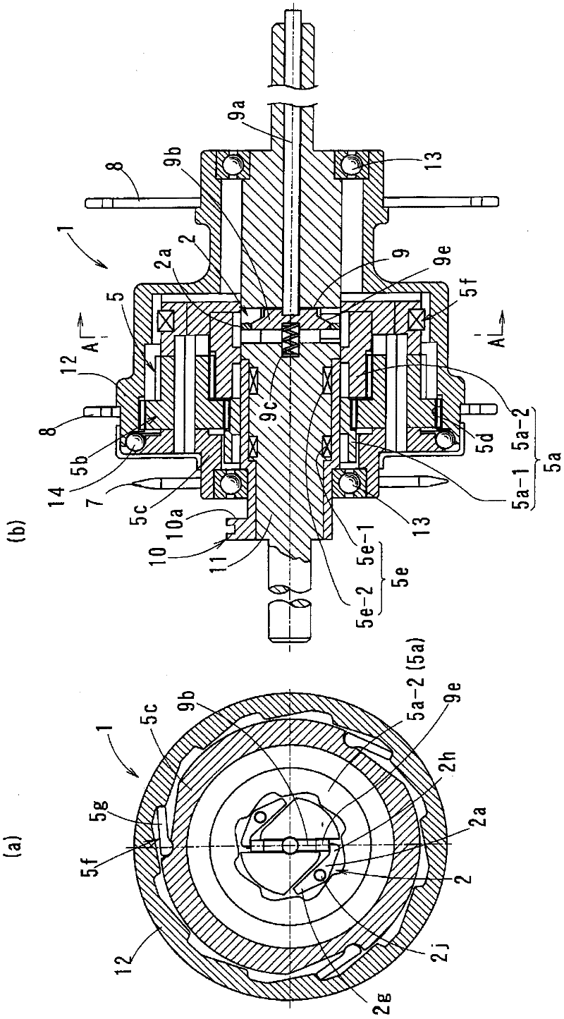
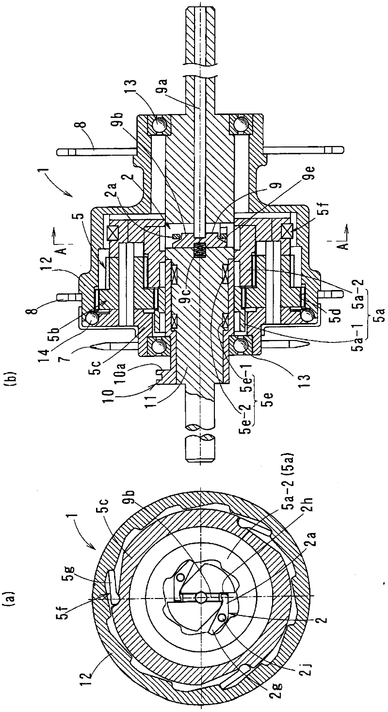
[0132] based on figure 1 as well as figure 2 A first embodiment of the present invention will be described. In the electrically assisted bicycle of this embodiment, a secondary battery and a motor for auxiliary driving (center motor unit C) are attached to the center motor of the frame connecting the front wheel and the rear wheel near the center between the front wheel and the rear wheel. way electric assist bike.

[0133] in addition, Figure 27 It is a side view showing an example of a motor-assisted bicycle B in each of the following embodiments. This power-assisted bicycle B transmits the pedaling force acting on the pedal 70 to the axle 5 of the rear wheel 75 through the driving force transmission member from the crankshaft 71 to the front sprocket 74, the chain 73, and the rear sprocket 4. The transmission member assists traveling by combining the pedaling force described above with the output from the motor.

[0134] Center motor unit C as Figure 27 As shown, i...

no. 2 approach

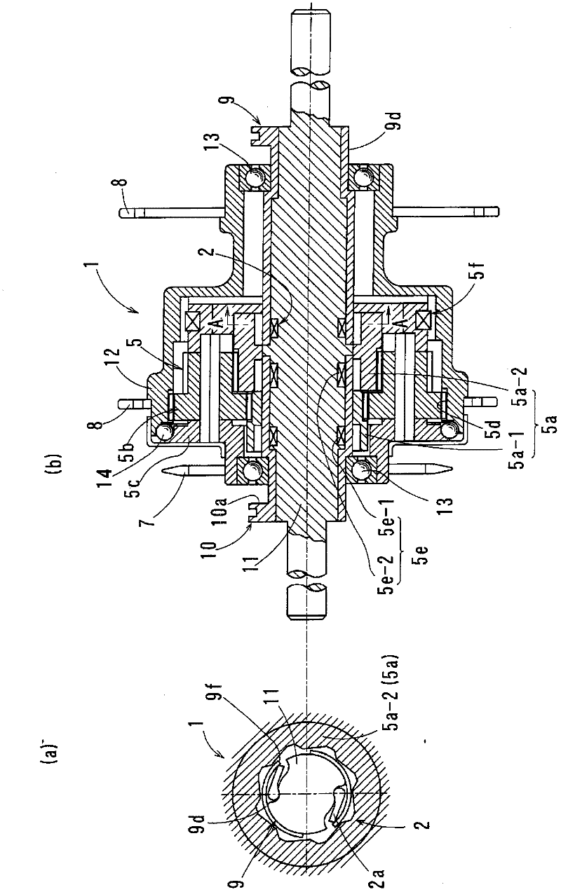
[0174] image 3 as well as Figure 4 A second embodiment of the present invention is shown. In this embodiment, the reverse input one-way clutch 2 is constituted by a ratchet clutch similarly to the first embodiment, but the clutch switching device 9 is mainly constituted by a rotating member 9d arranged along the axle 5 . Other main structures are the same as those of the first embodiment.

[0175]In this embodiment, the rotating member 9 d is a cylindrical member provided along the outer periphery of the axle 5 , and the rotating member 9 d is relatively rotatable around the axle 11 . And 9 f of rotating members are provided in the middle of the circumferential direction with 9 f of slits.

[0176] Usually, such as image 3 As shown in (a), the clutch pawl 2a of the one-way clutch 2 for reverse input is in the state forcibly pressed down by the said rotating member 9d.

[0177] Here, when the rotating member 9d is operated to rotate in the circumferential direction rela...

no. 3 approach

[0186] Figure 5 as well as Figure 6 A third embodiment of the present invention is shown. In this embodiment, a roller clutch is used to constitute the one-way clutch 2 for reverse input. Other main structures are the same as those of the second embodiment.

[0187] The description will focus on the structure of the one-way clutch 2 for reverse input, such as Figure 5 As shown, the second sun gear 5a-2 is used as the outer ring 2d of the roller clutch, the axle 11 is used as the inner ring 2c, and the cam surface 2i for engaging the roller 2a' is provided on the side of the axle 11 serving as the inner ring 2c.

[0188] Furthermore, the retainer 2d of the roller 2c is directly connected to the rotating member 9d of the clutch switching device 9 described above.

[0189] In this structure, usually, the roller 2a' is positioned at a wedge-shaped extended position in the wedge-shaped section formed by the cam surface 2i of the inner ring 2c and the inner peripheral surface...


PUM


Abstract

Provided is a power-assisted bicycle of the central motor type including a hub gear and capable of regenerative charging without complicating the system. A hub (1) on a driving wheel includes a gear change mechanism (5) including a planetary gear mechanism, a one-way clutch (2) for reverse input, and a clutch switching unit (9). The gear change mechanism (5) has at least one sun gear (5a), and transmits driving force to the driving wheel via a sprocket (7). The gear change mechanism also includes a gear change control mechanism (10) that changes gears by switching the sun gear (5a) between being rotatable about an axle (11) and non-rotatable in response to the driving force. The one-way clutch (2) for reverse input is disposed between the at least one sun gear (5a) and the axle (11), and the clutch switching unit (9) switches the sun gear (5a) between being rotatable about the axle (11) and non-rotatable in response to a reverse input. The clutch switching unit (9) sets the one-way clutch (2) for reverse input to be rotatable while the bicycle is being driven so that the driving force is transmitted and to be non-rotatable while the bicycle is moving forward but not being driven so that the reverse input torque is transmitted to the sprocket (7).

Description

technical field [0001] The present invention relates to an electric assist bicycle which utilizes an electric motor to apply assist force to a human drive system. Background technique [0002] In a power-assisted bicycle that uses an electric motor to apply assist force to a human-powered drive system, a battery is mounted as a power source for the motor for imparting electric assist force. The battery is expected to be able to run for a long time on a single charge, and therefore, a power-assisted bicycle has been developed that effectively utilizes energy during self-running and charges the battery by regenerative power generation during the self-running. [0003] As a battery charging device based on regenerative power generation, for example, Patent Document 1 discloses a technology of a regenerative control device that detects an operation of a brake lever and instructs a regenerative device to perform a regenerative operation (see, for example, Patent Document 1). [...

Claims


Application Information

Patent Timeline
Patent Type & Authority Applications(China)
IPC IPC(8): B62M6/55B62M11/16F16D41/24
CPCB62M11/16B62M6/55F16D41/30
Inventor 前野荣二伊藤洁洋
Owner NTN CORP
Why Eureka
Try Eureka