Damping control device

A control device, feedback control technology, applied in the direction of control devices, battery/fuel cell control devices, power devices, etc., can solve the problem of unstable vehicle conditions and achieve the effect of suppressing the impact

Active Publication Date: 2012-04-18
TOYOTA JIDOSHA KK
View PDF1 Cites 7 Cited by
  • Summary
  • Abstract
  • Description
  • Claims
  • Application Information

AI Technical Summary

Problems solved by technology

When the lateral reaction force of each wheel changes in this way, the balance of the lateral reaction force of the vehicle as a whole may change, but when the balance of the lateral reaction force of the vehicle as a whole changes, the condition of the vehicle may become unstable

Method used


Image

  • Damping control device
  • Damping control device
  • Damping control device

Examples


Embodiment 1

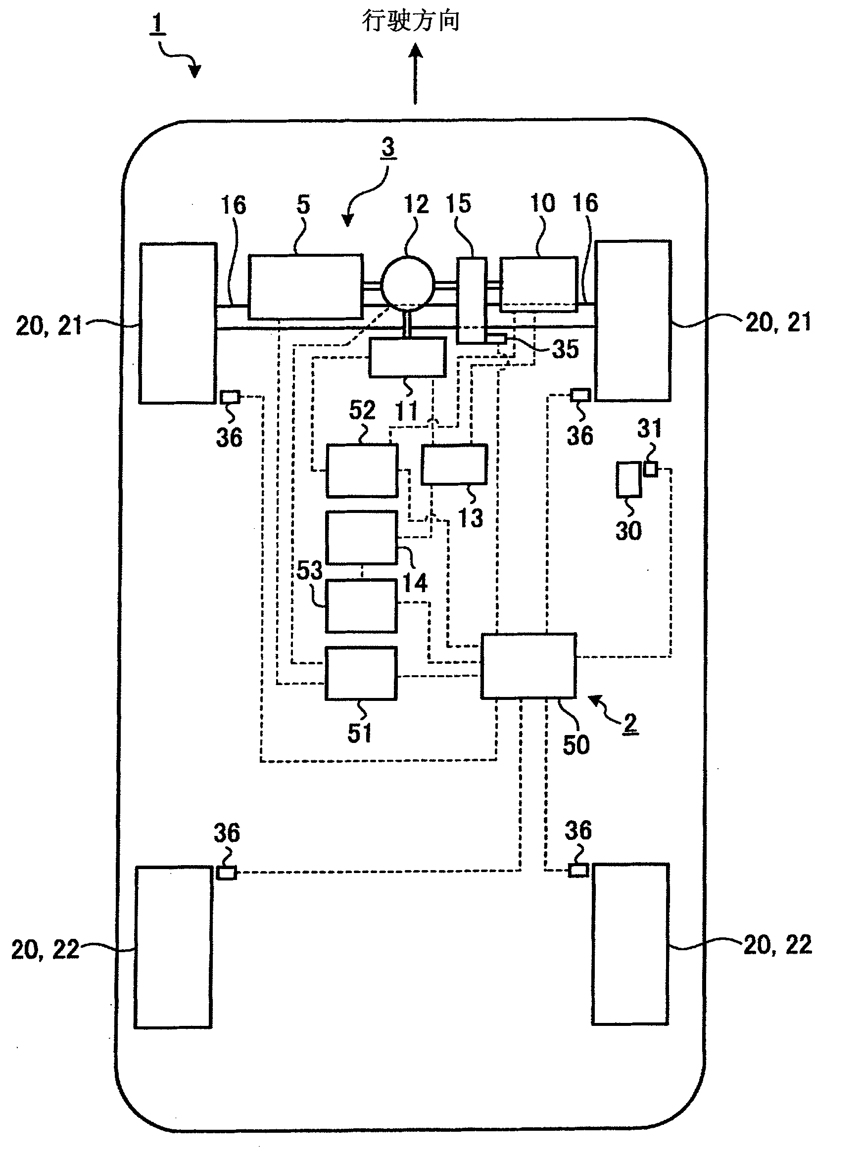
[0081] figure 1 It is a schematic diagram of main parts of a vehicle provided with the vibration damping control device according to Embodiment 1 of the present invention. In the following description, the traveling direction when the vehicle 1 normally travels is referred to as the front, and the direction opposite to the traveling direction is referred to as the rear. In addition, the sprung vibration in the following description refers to the vibration generated on the vehicle body via the suspension due to the input from the road surface to the wheels of the vehicle, for example, vibration of frequency components in the vicinity of 1 to 4 Hz, more specifically 1.5 Hz. The sprung vibration of the vehicle includes a component in the pitch direction or the jump direction (up-down direction) of the vehicle. In addition, sprung vibration damping refers to a technique for suppressing the above-mentioned sprung vibration of the vehicle.

[0082] figure 1 The shown vehicle 1 is...

Embodiment 2

[0123] The vibration damping control device 90 of the second embodiment has substantially the same configuration as the vibration damping control device 2 of the first embodiment, but is characterized by including the voltage of the battery 14 as the execution condition of the sprung vibration damping. The other configurations are the same as those in Embodiment 1, so descriptions thereof are omitted, and the same reference numerals are attached. Figure 5 It is a configuration diagram of main parts of the vibration damping control device of the second embodiment. Regarding the vibration damping control device 90 of the second embodiment, similar to the vibration damping control device 2 of the first embodiment, whether the engine 5 is started or stopped is used to determine whether to prohibit the sprung vibration damping control. In the vibration damping control device 90 of 2, the voltage of the battery 14 is also used in the judgment of whether to prohibit the sprung vibra...

Embodiment 3

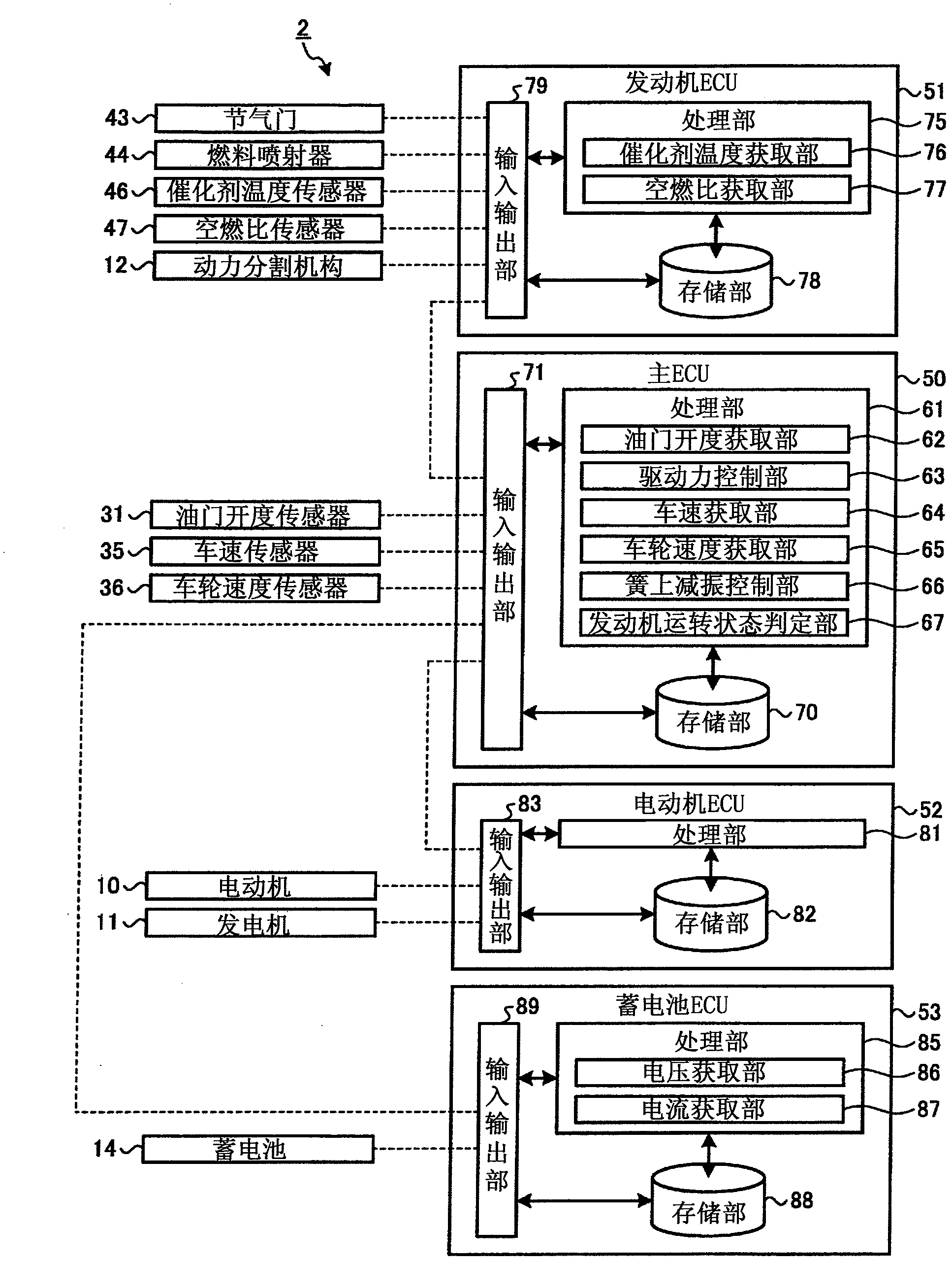
[0139] The vibration damping control device 100 of the third embodiment has substantially the same configuration as the vibration damping control device 2 of the first embodiment, but has a disadvantage in that it determines whether to execute the sprung vibration damping based on the presence or absence of the catalyst 45 warm-up request. feature. The other configurations are the same as those in Embodiment 1, so descriptions thereof are omitted, and the same reference numerals are attached. Figure 8 It is a configuration diagram of main parts of the vibration damping control device of the third embodiment. The vibration damping control device 100 of the third embodiment uses whether or not there is a request to warm up the catalyst 45 in determining whether to prohibit the sprung vibration damping control. Therefore, in the vibration damping control device 100 of Embodiment 3, the processing unit 61 of the main ECU 50 has an accelerator opening acquisition unit 62, a drivi...


PUM


Abstract

Spring-damping operations for suppressing the springing vibrations which are generated in a vehicle (1) by the input from the road surface to the wheels (20) of the vehicle (1) are performed by controlling the torque of a motor (10). The spring-damping operations are restricted or inhibited in accordance with either the state of a battery (14) such as the voltage and the temperature of the battery (14) for feeding the electric power to the motor (10), or the state of the control such as a charge / discharge feedback control which influences the electric power of the battery (14). As a result, the spring-damping operations can be restricted in the case of the state where the springing vibrations may be hard to perform properly, where the battery (14) is easily deteriorated or where an interference with another control may occur. Thus, the spring-damping operations can be executed in the state where the control of the operations is conceded, if necessary, so that the spring-damping control and other controls can be properly executed. As a result, it is possible to prevent the spring-damping control from influencing the other controls.

Description

technical field [0001] The invention relates to a vibration damping control device. In particular, the present invention relates to a vibration damping control device for suppressing vibration on the side of a vehicle body relative to a suspension device of a vehicle. Background technique [0002] During the running of the vehicle, sometimes due to the driving operation performed by the driver or the disturbance during the running of the vehicle, the vibration on the side of the vehicle body than the suspension of the vehicle, that is, the so-called sprung vibration, may cause the attitude of the vehicle to change. This attitude change causes the ground contact load of each wheel to change. The ground contact load affects the lateral reaction force generated at the wheels. Therefore, when the ground contact load of each wheel changes, the lateral reaction force of each wheel changes along with the change of the ground contact load. When the lateral reaction force of each w...

Claims


Application Information

Patent Timeline
Patent Type & Authority Applications(China)
IPC IPC(8): B60L15/20B60K6/445B60W10/08B60W10/26B60W20/00B60K6/44B60L50/16B60W10/06B60W30/02F01N3/24
CPCY02T10/6239Y02T10/6286B60W2550/147B60W2510/246B60W10/06B60W2510/22B60W2510/244B60K6/445Y02T10/7291Y02T10/7005B60L11/1851B60K6/365Y02T90/16B60W20/00B60W30/20Y02T10/7258B60K1/02Y02T10/705B60L2240/647B60W10/26B60W30/025B60W10/08B60L58/10B60W2552/35Y02T10/62Y02T10/70Y02T10/72B60W2422/40
Inventor 木下刚生牟田浩一郎山本雅哉福代英司尾山俊介桥本俊哉青木孝典木村秋广
Owner TOYOTA JIDOSHA KK
Why Eureka
Try Eureka