

Pile cutting construction method of bored concrete pile
A construction method and technology of cast-in-situ piles, which are applied in sheet pile walls, foundation structure engineering, construction, etc., can solve the problems of large number of drilling holes and silent breakers, low construction efficiency, and high construction cost, so as to save engineering cost and environment Less pollution and less impact on the environment
Active Publication Date: 2012-04-25
ZHEJIANG UNIV CITY COLLEGE +1
View PDF7 Cites 43 Cited by
- Summary
- Abstract
- Description
- Claims
- Application Information
AI Technical Summary
Problems solved by technology
In China, after drilling with a hand-held pneumatic drill, the pile head is broken into blocks by embedding a silent breaker. However, the hole diameter of reinforced concrete needs to be 40-50mm and the hole dista
Method used
View moreImage
Smart ImageViewing Examples

Examples
 PUM
 Abstract
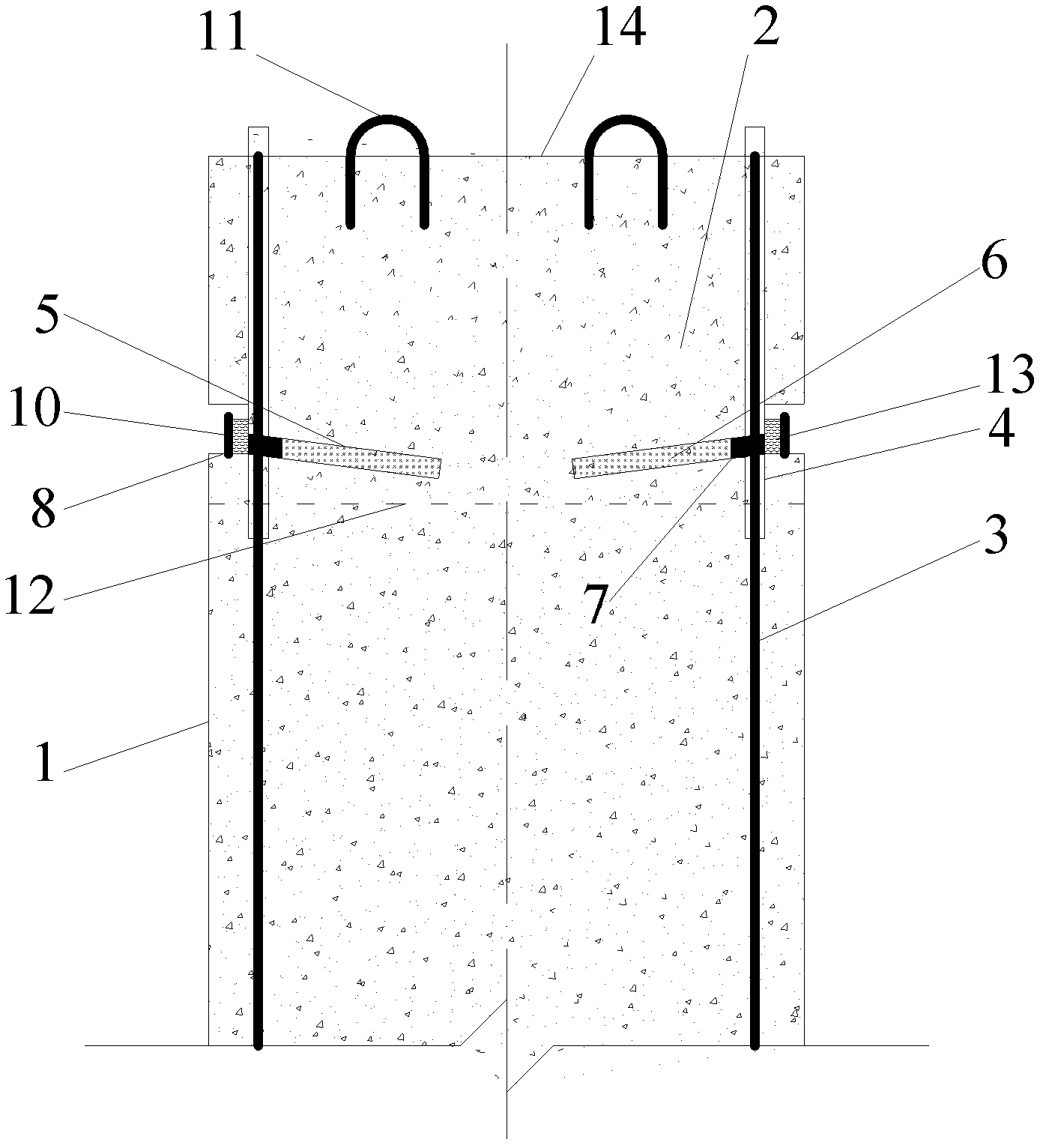
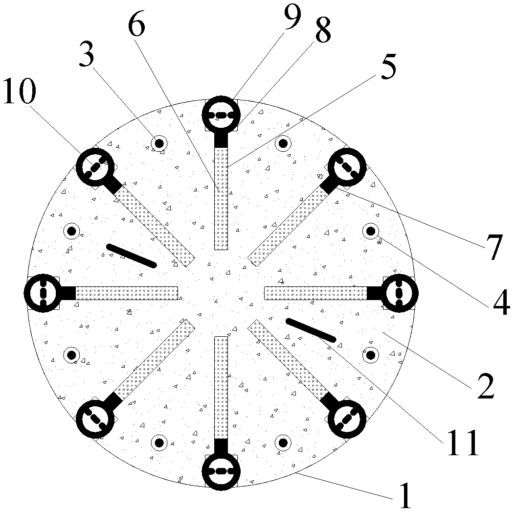
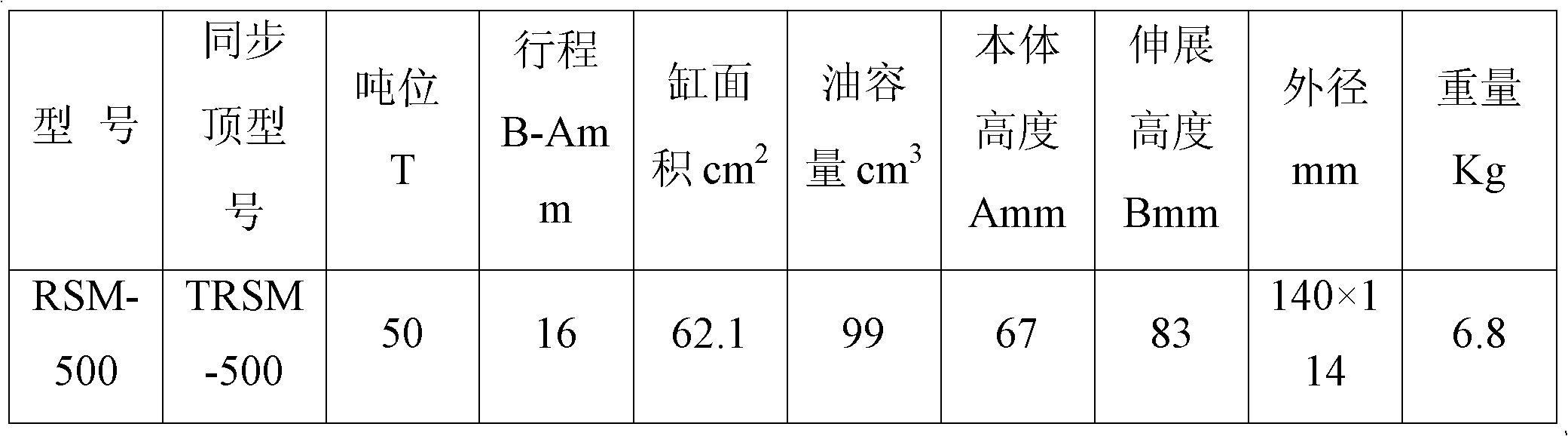
The invention provides a pile cutting construction method of a bored concrete pile, comprising the following steps of: sleeving a protective barrel with grooves on a pore top prior to filling pile body concrete to the bored concrete pile; placing a steel reinforcement cage after arranging an isolation casing on a vertical main rib of the steel reinforcement cage on the pile top of the bored concrete pile; filling concrete into the bored concrete pile to obtain the pile; implanting a lifting ring on an over-filled top; after meeting a concrete curing demand, disassembling the protective barrel with the grooves; when the pile body reaches a design strength standard value by 70%, drilling pores at parts on the pile body, corresponding to the grooves of the protective barrel, to form filling pores above a pile top design standard; filling a soundless cracking agent into the pores, wherein the soundless cracking agent functions as expansion to cut down the over-filled pile top in combination with a thinned synchronous jack placed in the grooves. Compared with the traditional methods such as pile cutting with the soundless cracking agent, manual chiseling and pile cracking by hydraulic crushing and the like, the pile cutting construction method disclosed by the invention has the advantages of fast construction speed, low manufacture cost, small influence to the environment and better technical and economic benefits.
Description
technical field [0001] The invention relates to a method for cutting off the super-filled portion of a cast-in-situ pile higher than the design elevation of the pile top, in particular to a method for cutting piles in combination with a soundless breaking agent and a synchronous thin jack. Background technique [0002] "Code for Construction Quality Acceptance of Building Foundation Engineering" (GB50208-2002) stipulates that the pile top elevation of cast-in-place piles should be at least 0.5m higher than the design elevation; The concrete superfill height of cast-in-situ piles has also been specified. The specification stipulates that the amount of pouring of pile foundation concrete is large at one time, or the foundation pile of concrete poured underwater, because the air bubbles or pores inside the concrete rise to the top of the pile during the vibration process, the pile top will be laitance within a certain range. 1. Mud or mortar mixture during underwater concrete ...
Claims
Login to View More Application Information
Patent Timeline
 IPC IPC(8): E02D5/38E02D9/00
Inventor王新泉陈永辉陈龙陈庚
OwnerZHEJIANG UNIV CITY COLLEGE