
Inductive plugging device

A technology for sensing sockets and plugs, applied in the direction of two-part connection devices, parts of the connection device, coupling devices, etc., can solve problems such as electric shock, poor safety of sockets and plugs, and the body may touch the contact head of the socket.

Inactive Publication Date: 2012-05-09
国网河南修武县供电公司 +1
View PDF4 Cites 14 Cited by
  • Summary
  • Abstract
  • Description
  • Claims
  • Application Information

AI Technical Summary

Problems solved by technology

[0003] In the field of electric power, the sockets and plugs currently used are in direct electrical contact, and the voltage of the contact head in the socket is equal to the grid voltage, generally 220V or 380V. In the process of plugging the plug into the socket, arcs often occur The reason is that the pins of the plug are relatively close to the contact head in the socket, and when there is only a small gap, the voltage breaks down the air gap and forms an arc. In fact, the current socket and plug will have an instantaneous arc when they are in use. In humid weather and other conditions, when the contact between the socket and the plug is relatively wet, the arc phenomenon will be more obvious, and may even cause electric shock
In addition, the ordinary socket contact head is connected with the outside world. Due to various reasons of negligence or ignorance of children, the human body may touch the socket contact head, which will cause electric shock. During the process, due to the large exposed part of the plug pins, it is very likely that the human hands will accidentally touch the pins and cause an electric shock.
[0004] In summary, the current sockets and plugs are less safe

Method used


Image

  • Inductive plugging device
  • Inductive plugging device

Examples


Embodiment Construction

[0010] Below in conjunction with accompanying drawing and embodiment the present invention is further described:

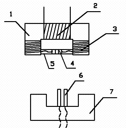
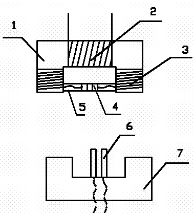
[0011] In the embodiment shown in the drawings, the induction socket and plug include a shell (not shown in the figure), socket core 1, input coil 2, output coil 3, circuit jack 4, circuit pin 6, plug core 7 , the shell includes a socket shell and a plug shell, the socket core 1 is a rectangle with one side open, the input coil 2 and the output coil 3 are wound on each side of the socket core 1, and the input The coil 2 is connected to the input end of the power grid, and the output coil 3 is connected to the circuit jack 4. The shape of the plug core 7 has the following characteristics: it can be spliced ​​with the socket core 1 to form a complete rectangular core , the shape and position of the circuit pin 6 has the following characteristics: when the plug core 7 and the socket core 1 are spliced ​​into a complete rectangular core, the circuit pin 6 has been in...


PUM


Abstract

The invention provides an inductive plugging device which comprises a shell, a socket iron core, an input coil, an output coil, circuit jacks, circuit pins and a plug iron core, wherein the socket iron core is a rectangle with one open side; the input coil and the output coil are wound on each side of the socket iron core; the input coil is connected with an input end of the power grid; the output coil is connected with the circuit jacks; the shape of the plug iron core is characterized in that the plug iron core can be spliced with the socket iron core to form an integrated rectangular iron core; and the shape of the circuit pins is characterized in that when the plug iron core and the socket are closed, the circuit pins are inserted into the circuit jacks, and the circuit pins are connected with an output lead wire. The inductive plugging device can normally supply power for electrical appliances, and completely remove electric arc danger and electric shock hazard, so that the security of the device is very high.

Description

Technical field [0001] The invention relates to the field of electric power, in particular to an induction socket and plug with high safety, electric shock prevention and arc prevention. [0002] Background technique [0003] In the field of electric power, the sockets and plugs currently used are in direct electrical contact, and the voltage of the contact head in the socket is equal to the grid voltage, generally 220V or 380V. In the process of plugging the plug into the socket, arcs often occur The reason is that the pins of the plug are relatively close to the contact head in the socket, and when there is only a small gap, the voltage breaks down the air gap and forms an arc. In fact, the current socket and plug will have an instantaneous arc when they are in use. In humid weather and other conditions, when the contact between the socket and the plug is relatively wet, the arc phenomenon will be more obvious, and may even cause electric shock. In addition, the ordinary...

Claims


Application Information

Patent Timeline
Patent Type & Authority Applications(China)
IPC IPC(8): H01R13/66H01R24/00H01F3/02
Inventor 郭金猷
Owner 国网河南修武县供电公司
Learn More