Intelligent card for mobile phone getting electricity by lithium battery of the mobile phone

A technology for smart cards and mobile phones, applied in the field of smart cards of mobile phones, can solve the problems of inability to identify the radio frequency module to supply power, no space reserved for power supply of the identification radio frequency module, and inability to expand the power supply of the module, so as to meet the needs of power supply.

Active Publication Date: 2014-07-02
EASTCOMPEACE TECH
View PDF3 Cites 0 Cited by
  • Summary
  • Abstract
  • Description
  • Claims
  • Application Information

AI Technical Summary

Problems solved by technology

For example, if you want to realize smart payment, you need the support of RF-SIM card, and you need a module that can identify the radio frequency tag to support it. Since the identification radio frequency module itself needs power supply, however, there is no reserved space in the mobile phone for the identification of the radio frequency module. There is no space for power supply, so it is unable to provide corresponding power for the identification radio frequency module
There are also corresponding problems with other expansions of smartphone functions, that is, the corresponding power cannot be provided for the expansion module, so that the user's demand for smartphone expansion cannot be met.

Method used


Image

  • Intelligent card for mobile phone getting electricity by lithium battery of the mobile phone
  • Intelligent card for mobile phone getting electricity by lithium battery of the mobile phone
  • Intelligent card for mobile phone getting electricity by lithium battery of the mobile phone

Examples


Embodiment Construction

[0022] The following will clearly and completely describe the technical solutions in the embodiments of the present invention with reference to the accompanying drawings in the embodiments of the present invention. Obviously, the described embodiments are only some, not all, embodiments of the present invention. Based on the embodiments of the present invention, all other embodiments obtained by persons of ordinary skill in the art without creative efforts fall within the protection scope of the present invention.

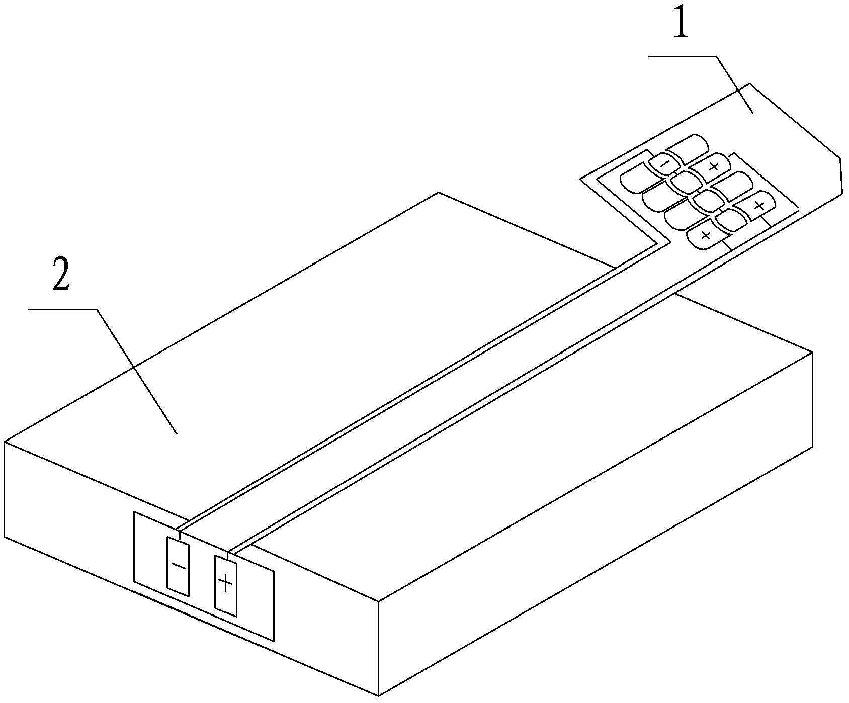
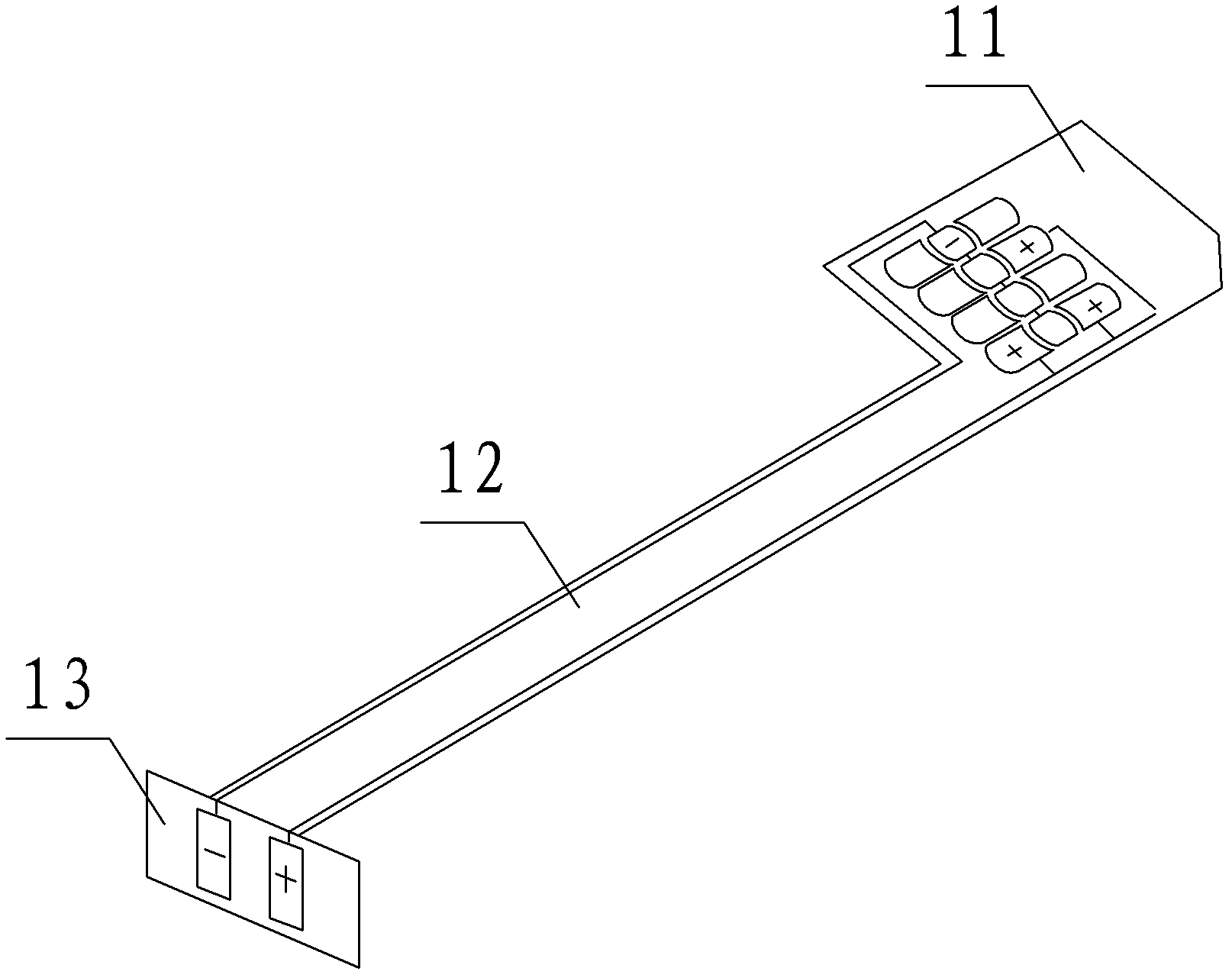
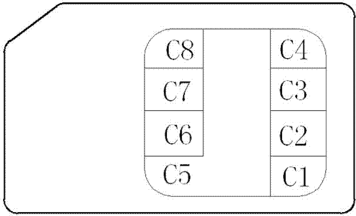
[0023] An embodiment of the present invention provides a smart card for a mobile phone, which includes a smart card body with multiple pins, a connection board, and a power-taking board; the spare pins of the smart card body are connected to the positive end of the power-taking board through the connection board , the zero potential end of the smart card main body is connected to the negative terminal of the power-taking plate; The negative end of the electric shee...


PUM


Abstract

The invention discloses an intelligent card of a mobile phone, which comprises an intelligent card main body with a plurality of pins, a connection plate and an electricity taking plate, wherein the standby pin of the intelligent card main body is connected with the anode end of the electricity taking plate through the connection plate, the zero potential end of the intelligent card main body is connected with the cathode end of the electricity taking plate, the anode end of the electricity taking plate is respectively connected with the electricity anode end of the mobile phone and the anode end of a battery of the mobile phone, the cathode end of the electricity taking plate is respectively connected with the electricity taking cathode end of the mobile phone and the cathode end of the battery of the mobile phone, the standby pin of the intelligent card main body is connected with the anode end of an expansion device of the mobile phone, the zero potential end of the intelligent card main body can be connected with the cathode end of the expansion device of the mobile phone, the anode and the cathode of the electricity taking plate can be arranged at the connection positions of the electricity taking anode and the electricity taking cathode of the mobile phone and the anode and the cathode of the battery, the normal electricity supply of the battery for the mobile phone is not influenced, in addition, the anode and the cathode of the expansion device of the mobile phone are connected with the standby pin and the zero potential end of the intelligent card main body, so that the electricity supply requirements of the expansion device of the mobile phone can be met.

Description

technical field [0001] The invention relates to the field of smart phones, more specifically, to smart cards for mobile phones. Background technique [0002] With the popularization and enhancement of functions of modern smart phones, people have a strong demand for applications such as electronic payment, product authenticity identification and real-time positioning. [0003] For the expansion of additional functions of smart phones, the current mobile phone suppliers do not give timely updates on the hardware. For example, if you want to realize smart payment, you need the support of RF-SIM card, and you need a module that can identify the radio frequency tag to support it. Since the identification radio frequency module itself needs power supply, however, there is no reserved space in the mobile phone for the identification of the radio frequency module. There is no space for power supply, so the corresponding power cannot be provided for the identification radio frequen...

Claims


Application Information

Patent Timeline
Patent Type & Authority Patents(China)
IPC IPC(8): H04M1/02G06K19/077
Inventor 党飞杨军
Owner EASTCOMPEACE TECH
Why Eureka
Try Eureka