Power supply communication control circuit and power supply communication system

A technology for controlling circuits and communication information. It is applied in the parts of TV systems, image communication, and TV. It can solve the problems of complicated operation process and damage to cameras, and achieve the effect of broadening the scope of application.

Active Publication Date: 2019-01-11
ZHEJIANG DAHUA TECH CO LTD
View PDF11 Cites 0 Cited by
  • Summary
  • Abstract
  • Description
  • Claims
  • Application Information

AI Technical Summary

Problems solved by technology

However, under normal circumstances, the camera is often only provided with a power supply interface externally, and no external communication interface is provided. To enable the camera to realize the communication function, it is necessary to use the communication interface function of the internal communication module to lead the communication interface through a wire. The camera needs to be disassembled, making the operation process complicated and easily causing damage to the camera

Method used


Image

  • Power supply communication control circuit and power supply communication system
  • Power supply communication control circuit and power supply communication system
  • Power supply communication control circuit and power supply communication system

Examples


Embodiment 1

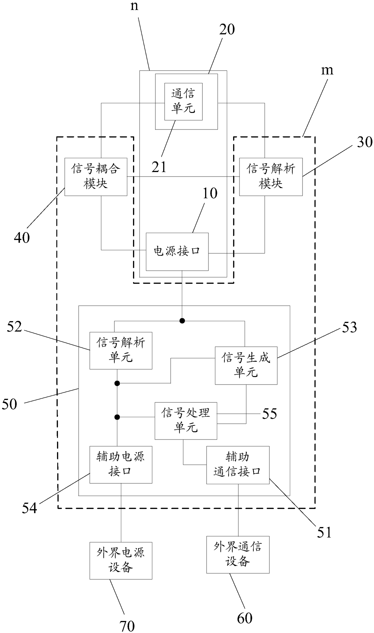
[0119] Embodiment one: see figure 2 In the shown structure, when it is determined that the communication function of the powered device is turned on, the process of the powered device outputting the second communication information to the external communication device is described.

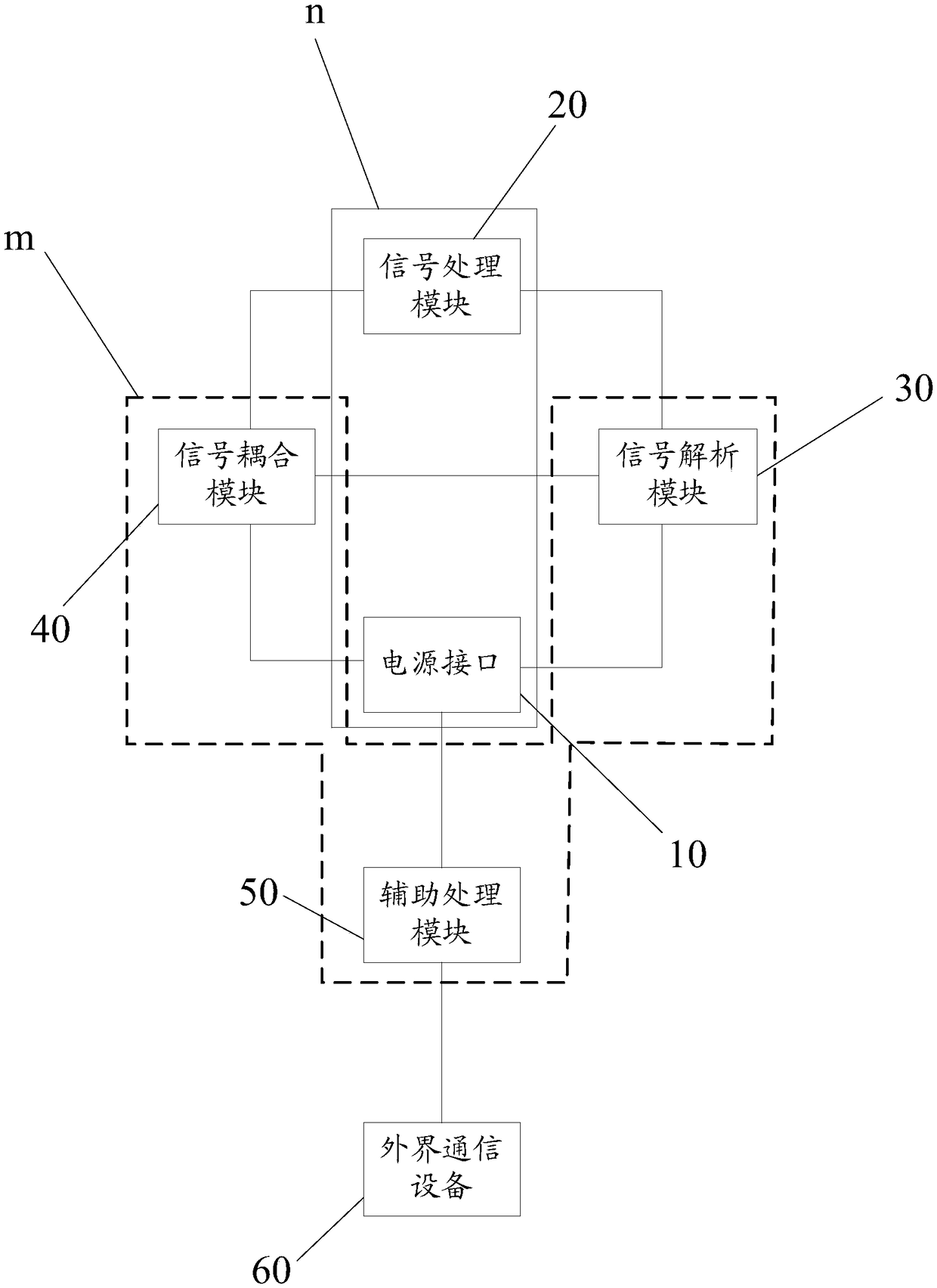
[0120] Step 1, the signal processing module outputs the second communication information to the signal coupling module through the communication unit;

[0121] Step 2, the signal coupling module couples the second communication information to the power signal provided by the signal analysis module to form a carrier signal and output it to the power interface;

[0122] Step 3, the power interface outputs the carrier signal to the signal analysis unit;

[0123] Step 4, the signal analysis unit extracts the second communication information from the carrier signal and outputs it to the signal processing unit;

[0124] Step 5: The signal processing unit outputs the second communication information t...

Embodiment 2

[0125] Embodiment two: see figure 2 In the shown structure, when it is determined that the communication functions of the powered device and the auxiliary processing module are both turned on, the process of the external communication device outputting the first communication information to the powered device is described.

[0126] Step 1, the signal processing unit receives the first communication information input through the auxiliary communication interface;

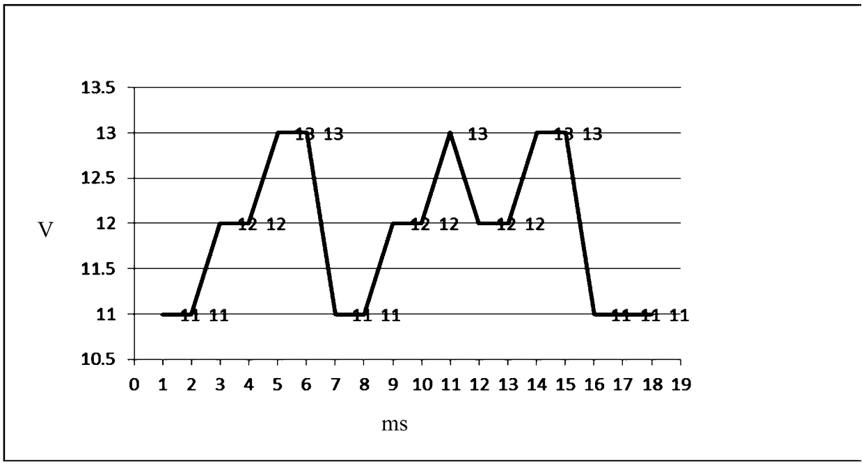
[0127] Step 2: The signal generation unit generates a third-order level signal carrying the first communication information according to a preset coding rule, and outputs it to the power interface;

[0128] Step 3, the power interface transmits the third-order level signal to the signal analysis module;

[0129] Step 4, the signal analysis module analyzes the first communication information from the third-order level signal according to the preset decoding rules, and transmits the first communication information to...


PUM


Abstract

The present invention discloses a power supply communication control circuit and a power supply communication system, and relates to the technical field of hardware. In the embodiment of the invention, through arrangement of a power supply communication control circuit, when it is determined that a powered device can communicate with an external communication device, a communication function between the powered device and the external communication device is opened to achieve the communication between the powered device and the external communication device in a condition that the powered device has a power source interface and has no a communication interface, namely, the power source interface of the powered device can achieve a communication interface function without influence of the normal power supply of the powered device so as to greatly widen the application range of the powered device.

Description

technical field [0001] The invention relates to the technical field of hardware, in particular to a power supply communication control circuit and a power supply communication system. Background technique [0002] The current camera is generally provided with a power interface externally, which is used for inputting an external power supply to provide power for the camera. Generally, a communication module is provided inside the camera, and the communication module can provide a communication interface function. However, under normal circumstances, the camera is often only provided with a power supply interface externally, and no external communication interface is provided. To enable the camera to realize the communication function, it is necessary to use the communication interface function of the internal communication module to lead the communication interface through a wire. The camera needs to be disassembled, which makes the operation process complicated and easily c...

Claims


Application Information

Patent Timeline
Patent Type & Authority Applications(China)
IPC IPC(8): H04N5/765H04L12/10
CPCH04L12/10H04N5/765
Inventor 徐礼伟饶东波
Owner ZHEJIANG DAHUA TECH CO LTD
Why Eureka
Try Eureka