Stereo audio system and audio-visual equipment

An audio system and stereo sound technology, applied in the audio-visual field, can solve the problems of uneven distribution of channels, small optimal listening position, and inability to maintain coherence and linearity of the sound field, so as to achieve the effect of coherent stereo field and better effect.

Active Publication Date: 2012-05-09
KONKA GROUP
View PDF3 Cites 6 Cited by
  • Summary
  • Abstract
  • Description
  • Claims
  • Application Information

AI Technical Summary

Problems solved by technology

However, the three-dimensional and surround effects presented by the audio system depend on the position of the listener relative to the sound channel, but the channel distribution of the two-channel, 5.1-channel and 7.1-channel technologies is not uniform enough, and the user cannot get a real listening experience
Especially when there are moving sound sources in TV programs and movies, the sound field cannot remain coherent and linear
[0004] Secondly, the sweet spot area of ​​the audio system using two-channel, 5.1-channel or 7.1-channel technology is small, which is not convenient for multiple people to listen to, making it impossible to guarantee that everyone can get the best experience when watching movies or listening to music
In addition, due to the limitation of the area of ​​the best listening position, the existing audio system has high requirements on the installation environment and technology when it is applied to home theater equipment or cinema projection equipment, and does not make use of marketing and application

Method used


Image

  • Stereo audio system and audio-visual equipment
  • Stereo audio system and audio-visual equipment
  • Stereo audio system and audio-visual equipment

Examples


Embodiment Construction

[0029] The following will further describe in detail with reference to the drawings and the embodiments of the present invention.

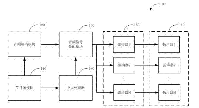
[0030] figure 1 This is a schematic diagram of the circuit modules of the stereo audio system 100 provided by the present invention. Such as figure 1 As shown, the stereo audio system 100 includes a program source module 110, an audio decoding module 120, a central processing unit 130, an audio signal distribution module 140, a power amplifier module 150, and a speaker module 160.

[0031] The program source module 110 is used to extract the audio source signal in the program source, and output the audio source signal to the audio decoding module 120 and the central processing unit 130. Wherein, the audio source signal includes original sound field information.

[0032] The audio decoding module 120 is configured to decode the audio source signal and output the audio signal to the audio signal distribution module 140. In other embodiments of the presen...


PUM


Abstract

The invention provides a stereo audio system and audio-visual equipment. A program source module of the stereo audio system is used for extracting and outputting a sound source signal of a program source. An audio decoding module is used for decoding the sound source signal and outputting the sound source signal. A loud-speaking module comprises a plurality of loudspeakers arranged above and at the periphery of a user; and the loudspeakers respectively correspond to a plurality of different sound channels. A power amplifier module comprises a plurality of power amplifiers which are mutually independent; and the power amplifiers are used for respectively pushing the loudspeakers in the loud-speaking module. An audio signal distributing module is used for distributing an audio signal to the power amplifiers in the power amplifier module, thereby driving the power amplifiers to push the loudspeakers in corresponding sound channels to sound. A central processing unit is used for controlling the audio signal distribution module according to an original sound field signal in the sound source signal. According to the stereo audio system and the audio-visual equipment provided by the invention, a loud-speaking array is arranged above and at the periphery of the use, thereby creating a stereo sound field with the better effect and enabling the stereo sound field to be coherent and linear.

Description

Technical field [0001] The present invention relates to the field of audiovisual technology, in particular to a stereo audio system and audiovisual equipment. Background technique [0002] With the continuous development of electronics and computer technology, the video technology in audio-visual equipment is improved due to the improvement of video algorithms (such as MEPG-4, H.264, etc.) and video equipment (such as LCD TV, LED TV, 3D TV, IMAX screen, etc.) , The user's visual experience has been greatly improved and improved. However, audio technology in audio-visual equipment still has shortcomings, it is difficult to restore the effects of natural sound sources, and cannot provide users with a high-quality listening experience. [0003] Existing audio systems usually use dual-channel, 5.1-channel and 7.1-channel technologies to simulate the stereo and surround effects of natural sound sources. However, the stereo and surround effects presented by the audio system depend on t...

Claims


Application Information

Patent Timeline
Patent Type & Authority Applications(China)
IPC IPC(8): H04R5/04H04N5/60
Inventor 于豪
Owner KONKA GROUP
Why Eureka
Try Eureka